AC vs DC
Two types of electric current exist in electronics: direct current (DC) and alternating current (AC). Understanding both is essential for ham radio because your station uses both every day — AC comes in from the line voltage and DC powers the equipment. Knowing how they differ, and why each is used where it is, makes everything from troubleshooting to safe operation much easier.
What Is DC (Direct Current)
Direct current flows in one direction continuously. The polarity — which terminal is positive and which is negative — stays fixed at all times. The voltage level may vary (a battery drops as it discharges, a solar panel varies with sunlight) but the direction of current flow never reverses.
Common DC sources in the ham shack and in everyday life:
- Batteries of all types: AA, AAA, 9 V PP3, sealed lead-acid, lithium-ion packs
- Regulated bench power supplies: output is a flat, stable DC level (e.g. exactly 13.8 V)
- USB power: 5 V DC from any USB port or charger
- Solar panels: DC output proportional to light intensity
- Vehicle electrical system: 12–14.4 V DC from battery and alternator
DC from a regulated supply is perfectly flat with no variation in level. DC from a battery drops slowly as energy is consumed. Pulsating DC — such as the output of a rectifier before a filter capacitor is added — rises and falls in magnitude but never reverses direction. This is still DC because the current never flows backwards.
All transistors, integrated circuits, digital logic, microcontrollers and RF amplifier stages inside a transceiver require a stable DC supply voltage to operate correctly.
What Is AC (Alternating Current)
Alternating current reverses direction periodically. The voltage starts at zero, rises to a positive peak, falls back through zero, continues to a negative peak, rises back to zero, and then repeats. One complete sequence from zero through both peaks and back to zero is called a cycle.
The number of cycles completed per second is the frequency, measured in hertz (Hz). Utility power in North America alternates at 60 Hz; in Europe, the UK, Africa, Australia and most of Asia it is 50 Hz. The waveform shape of line voltage AC is a sine wave — a smooth, mathematically pure oscillation. You will study sine waves in detail in the next lesson.
AC is also present in your radio station in forms other than utility power. Audio signals (300 Hz to 3 kHz) inside the microphone circuit, IF stages and audio amplifier are all AC. The RF signal on your antenna is AC at the transmit frequency — 14 MHz for 20 metres, 7 MHz for 40 metres and so on.
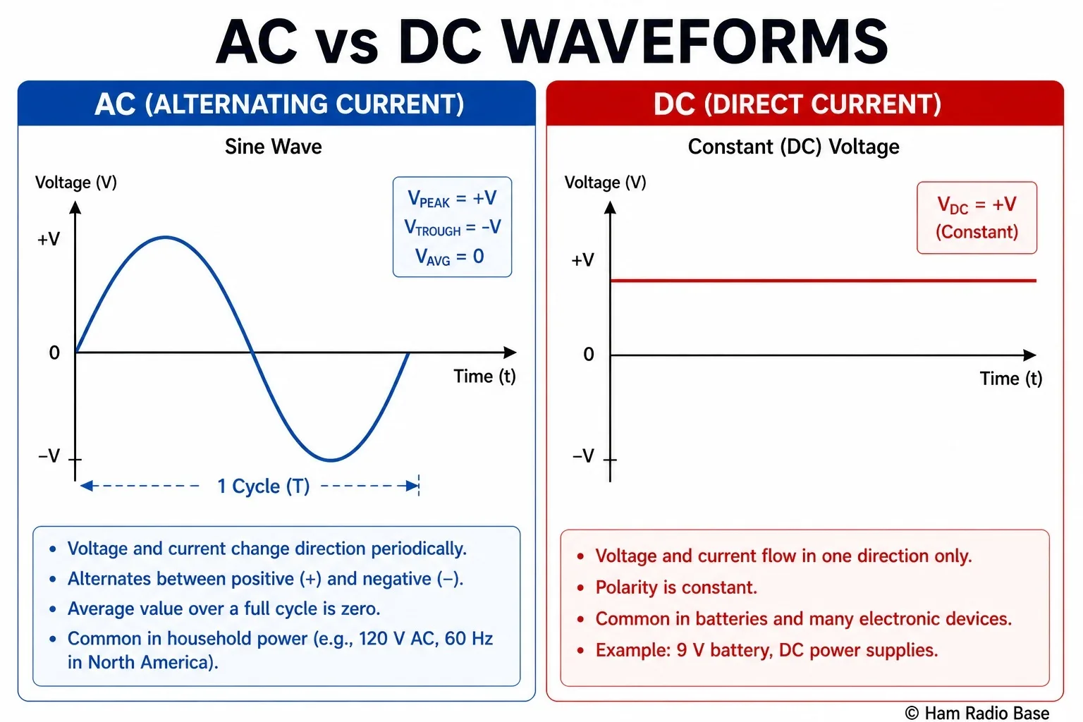
DC (right) is a constant, flat voltage. AC (left) oscillates above and below zero in a sine wave pattern.
Why AC for line voltage Power
If DC is what electronic equipment ultimately needs, why does the electricity grid distribute AC? There are compelling historical and technical reasons.
The key advantage of AC is the transformer. A transformer uses electromagnetic induction to step voltage up or down with very high efficiency — but it only works with AC. A changing magnetic flux (produced by AC) induces a voltage in the secondary winding. DC produces a static magnetic field that induces nothing after the initial transient.
Long-distance power transmission at high voltage is far more efficient than at low voltage. Consider the relationship P = V × I: to transmit the same power at a higher voltage, you need a proportionally lower current. Because resistive loss in a wire is Ploss = I² × R, halving the current reduces line losses by a factor of four. The electricity grid transmits power at hundreds of thousands of volts for this reason, then transformers at local substations step it down to the distribution voltage and finally to the 120 V or 230 V delivered to your premises.
This is why Nikola Tesla's AC system defeated Thomas Edison's DC proposal in the "War of Currents" of the 1880s and 1890s. Edison's DC grid required generating stations every mile or two because DC could not be stepped up efficiently. Tesla's AC grid, backed commercially by George Westinghouse, could transmit power over hundreds of miles from large, centralised generating stations.
DC long-distance transmission (HVDC — High Voltage Direct Current) is now technically feasible using modern solid-state power electronics, and is used in some submarine cable links and long overland routes. However, the existing AC infrastructure is so deeply established that AC utility supply will remain the standard for the foreseeable future.
Frequency and the Sine Wave
The line frequency determines how many times per second the voltage waveform passes through zero. At 60 Hz, the voltage crosses zero 120 times per second (twice per cycle — once going positive, once going negative). At 50 Hz it crosses zero 100 times per second.
The stated line voltage (120 V in North America, 230 V in Europe) is the RMS (Root Mean Square) value, not the peak value. The actual peak voltage is considerably higher:
120 V RMS → peak of approximately 170 V
230 V RMS → peak of approximately 325 V
RMS is a useful value because a DC voltage equal to the RMS value of an AC voltage delivers the same average power to a resistive load. You will cover the mathematics of sine waves, amplitude, RMS, period and wavelength in the next lesson. For now, the key point is that when an equipment data sheet says "120 V AC input", it means 120 V RMS.
Converting AC to DC — Rectification
All electronic equipment runs on DC internally, so the line voltage AC must be converted. This is what a power supply does. The conversion process has four stages:
- Transformer: steps the line voltage down (or up) to the required working level.
- Rectifier: one or more diodes allow current to flow in only one direction, converting the alternating AC into pulsating DC — voltage that fluctuates but never reverses.
- Filter capacitor: a large electrolytic capacitor smooths the pulsations into a much steadier DC level. Some residual ripple remains.
- Voltage regulator: sets the output to an exact, stable voltage regardless of load current or line voltage input variation. Modern regulators use integrated circuit devices and produce very clean DC output.
Your 13.8 V shack power supply contains all four of these stages, whether it is a traditional linear supply (with a large iron-core transformer) or a modern switch-mode supply. The transformer, rectifier and filter stages are covered in detail in Module 7 (Power Supplies). The important point at this stage is that the conversion always happens: line voltage AC in, stable DC out.
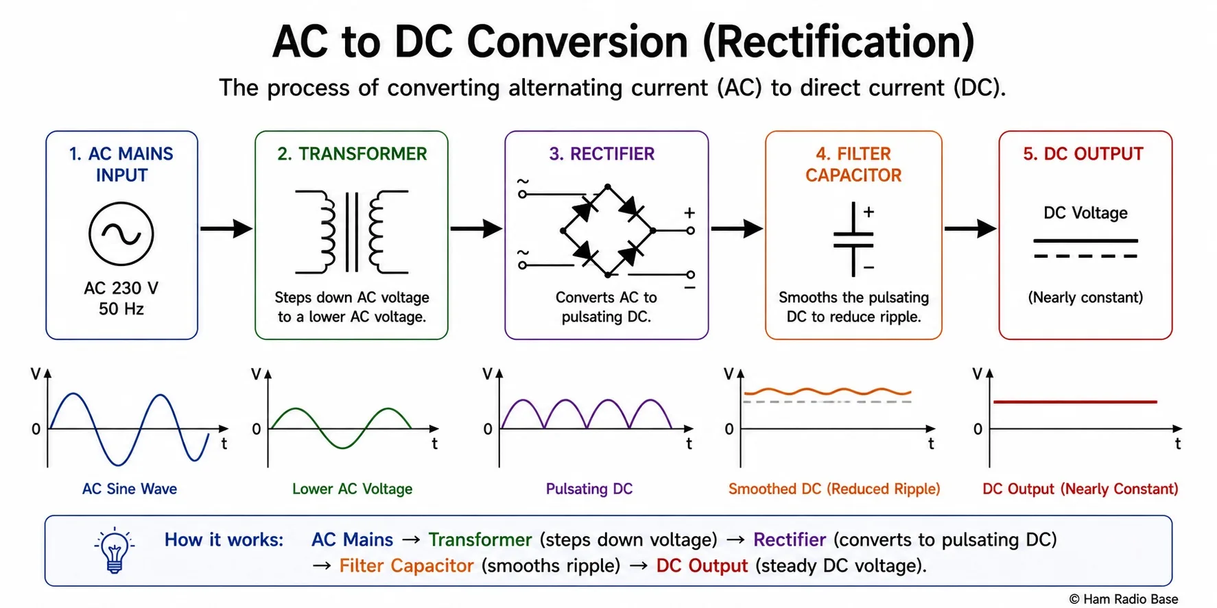
The four stages of AC-to-DC conversion: transformer, rectifier, filter capacitor, and voltage regulator.
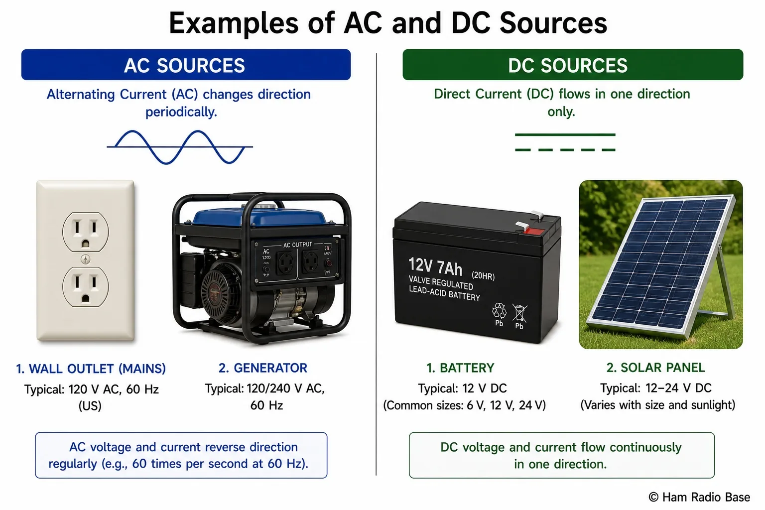
AC and DC sources you encounter every day: electrical outlet (AC), battery (DC), bench supply (DC from AC), vehicle outlet (DC).
AC and DC in Your Ham Shack
Understanding which type of current is present at each point in your station is essential for safe installation, fault-finding and equipment selection. Here is a practical breakdown:
| Location / Signal | Type | Typical Voltage / Frequency |
|---|---|---|
| line voltage wall socket | AC | 120 V / 60 Hz (NA) or 230 V / 50 Hz (EU/AU) |
| Shack power supply output | DC | 13.8 V regulated |
| Transceiver, amplifier, accessories | DC supply | 13.8 V DC input |
| Vehicle battery / alternator | DC | 12.0–14.4 V DC |
| Handheld radio battery | DC | 3.7–7.4 V DC (lithium cells) |
| RF voltage on antenna | AC (RF) | Transmit frequency (e.g. 14 MHz) |
| Audio signal in radio circuit | AC (audio) | 300 Hz–3 kHz (SSB voice) |
| Digital logic inside radio | DC | 3.3 V or 5 V logic levels |
The distinction between AC and DC becomes less clear at RF frequencies. A 14 MHz transmit signal is technically AC oscillating at 14 million cycles per second, but engineers and operators simply call it "RF." The same principle applies to audio: a microphone produces an AC voltage at audio frequencies, but we do not normally describe it that way in everyday speech.
The practical implication for safety: the utility supply is the most dangerous part of the station. Always treat electrical wiring as potentially live, even when switched off. Capacitors in power supplies can store lethal charge long after the supply is unplugged. DC voltages of 13.8 V are generally safe for skin contact, but the currents available from a large battery or supply can cause serious burn injuries through short circuits — always fuse your DC wiring.
Frequently Asked Questions
Why can't I just use AC to power my transceiver directly?
Transistors, integrated circuits and logic gates require a stable DC supply to operate. An AC input would reverse-bias every semiconductor junction 50 or 100 times per second, destroying the components. The power supply in your radio — or your external shack supply — exists specifically to convert the AC line voltage into stable, regulated DC. Some components like speakers and microphones do pass AC signals (audio), but even those are biased with DC in most circuits.
What is a power factor and does it matter in the shack?
Power factor (PF) is the ratio of real power (watts) to apparent power (volt-amperes, VA) in an AC circuit. In a purely resistive load (heater, incandescent bulb), PF = 1. Reactive loads (motors, transformers, switch-mode power supplies) draw current that is not perfectly in phase with the voltage, giving PF < 1. Most modern switch-mode power supplies (including the ones used for ham equipment) have power factor correction circuits that keep PF close to 1. For typical shack installations, PF is not something you need to calculate, but it explains why your 20 A-rated UPS might only support 1200 W of load rather than 2400 W.
What is the difference between 50 Hz and 60 Hz, and does it matter for ham equipment?
The line frequency is 50 Hz in most of Europe, Asia, Africa and Australia and 60 Hz in North America and parts of South America. Modern switching power supplies (the type used in most ham gear) work with any line frequency from 47 to 63 Hz and any voltage from about 90 to 264 V AC — the supply automatically detects and adapts. Older linear power supplies with large iron transformers were sometimes frequency-sensitive (50 Hz transformers run slightly warm on 60 Hz and vice versa) but this is rarely an issue for modern equipment. The line frequency does appear as hum in audio circuits if AC ripple is not properly filtered.
Can batteries deliver AC?
No — a battery is a DC source by nature; its terminals maintain fixed polarity. However, an inverter is an electronic circuit that takes DC from a battery and synthesises an AC output (commonly 120 V or 230 V at 50/60 Hz) using transistors switching rapidly. Inverters are used in vehicles and in off-grid systems to power line voltage-operated equipment. Quality inverters produce a clean sine wave output; cheaper ones produce a modified square wave that some equipment (especially those with inductive loads) may not tolerate well.
Test Your Knowledge
Answer the questions below to check your understanding. Every answer can be found in the lesson above.