Image Rejection and IF Selectivity
A superheterodyne receiver's performance ultimately depends on two numbers: how well it rejects signals at the image frequency (image rejection ratio), and how sharply it separates adjacent signals at the intermediate frequency (IF selectivity). Both are limited by physics — the IF frequency choice, the preselector filter design, the crystal filter Q — and both can be measured precisely. This lesson quantifies image rejection and IF selectivity, shows how each is calculated and what limits them, explains the shape factor that characterizes filter quality, and surveys the filter technologies used in modern amateur receivers from simple LC networks to DSP implementations.
Image Rejection Ratio (IRR)
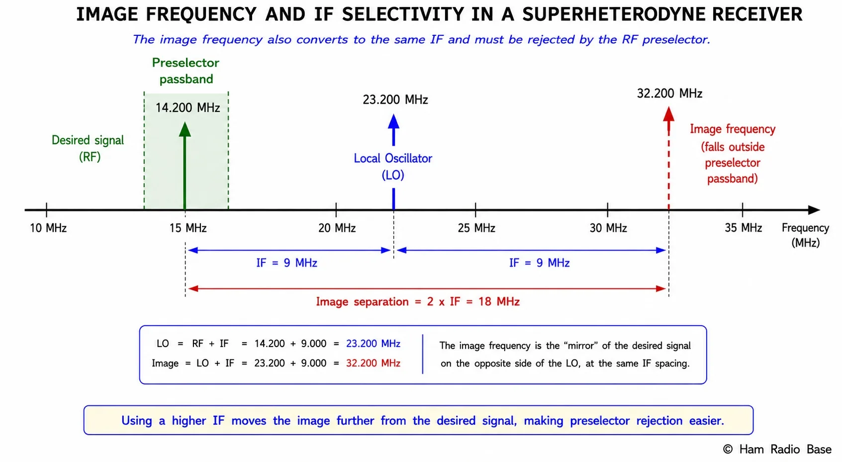
Image rejection ratio (IRR) quantifies how much the receiver attenuates a signal at the image frequency relative to a signal at the desired frequency. It is the combined attenuation from the preselector filter and any subsequent pre-IF filtering:
IRR (dB) = attenuation of preselector at fimage − attenuation of preselector at fRF
Typical values: 40–60 dB (consumer AM radios), 70–90 dB (amateur HF transceivers), >100 dB (high-performance receivers)
Receiver: 455 kHz IF, receiving 1,000 kHz (AM broadcast)
fLO = 1,000 + 455 = 1,455 kHz (high-side)
fimage = 1,000 + 2×455 = 1,910 kHz
Preselector is a single tuned circuit with Q = 50, centered at 1,000 kHz:
3 dB bandwidth = f / Q = 1,000,000 / 50 = 20 kHz
Attenuation at 1,910 kHz (910 kHz off center):
A ≈ 20 log(2Δf / BW3dB) = 20 log(2×910 / 20) = 20 log(91) ≈ 39 dB
This is modest image rejection — adequate for AM broadcast radio but poor for amateur HF use. A high-performance amateur receiver with a 45 MHz first IF has an image 90 MHz away — much easier to reject.
IF Frequency and Image Rejection
The image frequency is always 2×IF away from the desired signal. Doubling the IF doubles the frequency separation between desired signal and image, making the preselector filter's job much easier. This is the primary reason high-performance receivers use high first IFs:
| First IF | Image separation (2×IF) | Image rejection (typical preselector) | Common application |
|---|---|---|---|
| 455 kHz | 910 kHz | 30–50 dB | Consumer AM broadcast radio |
| 10.7 MHz | 21.4 MHz | 50–70 dB | Consumer FM radio |
| 9 MHz | 18 MHz | 60–80 dB | Older HF transceivers |
| 45 MHz | 90 MHz | 80–100 dB | Modern amateur HF transceivers |
| 70–75 MHz | 140–150 MHz | >100 dB | High-performance SDR receivers |
For an HF receiver covering 1.8–30 MHz with a 45 MHz first IF, the image falls at 1.8 + 90 = 91.8 MHz at the low end of the band, and at 30 + 90 = 120 MHz at the high end. A simple low-pass filter cutting off above 35–40 MHz provides 60+ dB of image rejection across the entire HF band — no tunable preselector required. This "roofing" approach, combined with a wide-bandwidth IF filter at the first IF, is the architecture used in the Icom IC-7300 and many SDR-based transceivers.
Shape Factor and Filter Selectivity
The shape factor (SF) of a filter describes how close to rectangular its frequency response is — how steeply it transitions from its passband to its stopband. A perfect rectangular filter would pass everything within its bandwidth and reject everything outside with infinite attenuation — shape factor = 1.0. Real filters have gradual transitions; their shape factor is always greater than 1.
SF = BW−60 dB / BW−3 dB
A shape factor of 1.5 means the filter's −60 dB bandwidth is 1.5× its −3 dB bandwidth.
IF filter: 2.4 kHz at −3 dB, 4.0 kHz at −60 dB
SF = 4.0 / 2.4 = 1.67
This is a good-quality crystal filter. A mediocre LC filter might have SF = 4–6 (the −60 dB bandwidth is 4–6× the −3 dB bandwidth), meaning it provides much less rejection of adjacent-channel signals just outside the passband.
| Filter Type | Typical Shape Factor (SF) | Notes |
|---|---|---|
| Single LC tuned circuit | 10–20 | Very gradual skirts; poor adjacent-channel rejection |
| Multiple LC stages | 3–8 | Improved but still poor compared to crystal filters |
| Ceramic IF filter | 2–4 | Used in low-cost AM/FM radios; adequate for consumer use |
| Crystal ladder filter | 1.5–2.5 | Standard for amateur HF transceivers; widely available |
| Monolithic crystal filter | 1.2–1.8 | Tight control of passband shape; used in premium transceivers |
| Mechanical filter | 1.05–1.3 | Excellent shape factor; heavy, expensive, limited to a few IFs |
| DSP FIR filter | 1.01–1.05 | Near-ideal shape factor; adjustable bandwidth; limited by ADC dynamic range |
IF Filter Technologies
LC Filters
Inductor-capacitor filters are tunable and inexpensive but have mediocre shape factors. Each stage contributes a second-order response; a Butterworth or Chebyshev LC filter needs 8–12 poles to achieve shape factors approaching 2.0. Used primarily in AM broadcast radios where a 10 kHz channel requires only modest selectivity.
Crystal Filters
Quartz crystals have Q values of 10,000–100,000 — orders of magnitude higher than LC circuits. A crystal ladder filter with 6–8 crystals achieves shape factors of 1.5–2.0 in a small package. The center frequency is fixed by the crystal cut — different bandwidth versions require different crystal cuts. Crystal filters are the workhorses of amateur HF IF strips: 2.4 kHz for SSB, 500 Hz for CW, 250 Hz for narrow CW.
Mechanical Filters
Mechanical filters (Collins design) use a series of metallic discs connected by thin coupling rods. Mechanical resonance at a fixed IF (typically 455 kHz) provides extremely high Q and excellent shape factors of 1.05–1.3. They are large, heavy, and produced only in a few frequencies — no longer made in quantity but still prized in vintage high-performance receivers.
DSP Filters
In SDR-based receivers, the IF signal is digitized by a high-speed ADC and all filtering is performed in software using FIR (finite impulse response) or IIR (infinite impulse response) algorithms. DSP filters can approach shape factors of 1.01 — nearly ideal rectangles — with fully adjustable bandwidth and center frequency. The limitation is ADC dynamic range: a 16-bit ADC provides about 96 dB of dynamic range, and strong out-of-band signals can saturate the ADC before the digital filter can reject them. High-performance SDR receivers use 24-bit ADCs and careful RF filtering to maximize dynamic range.
Adjacent-Channel Selectivity
Adjacent-channel selectivity (ACS) is the IF filter's ability to reject a signal on the immediately adjacent channel while receiving the desired signal at full strength. It is measured by applying the desired signal at the IF center frequency, then applying an interfering signal on an adjacent channel (typically 5, 10, or 20 kHz away for HF; 25 kHz for VHF FM) and measuring how much the interferer must be increased to produce a specified degradation in the desired signal output.
Desired signal: 0 dBm at 8.215 MHz
Interferer: applied at 8.217.4 MHz (+2.4 kHz offset, just outside 3 dB passband edge)
ACS: the interferer must be at least +30 dB above the desired signal to degrade SNR by 3 dB
For a filter with SF = 1.5 (BW−60dB = 3.6 kHz), a signal at 1.8 kHz off center is at the 60 dB rejection point — well attenuated.
Reading Receiver Specifications
When evaluating a receiver's published specifications, look for these key performance numbers:
| Specification | What it measures | Good value (amateur HF) |
|---|---|---|
| Sensitivity (MDS) | Minimum discernible signal (−3 dB SNR) | −130 to −140 dBm in 500 Hz BW |
| Noise figure (NF) | Receiver noise relative to thermal noise floor | 10–15 dB for HF; lower is better |
| Image rejection | Attenuation of image-frequency signals | >70 dB; >90 dB for premium receivers |
| IF rejection | Attenuation of signals at the IF frequency arriving at the antenna | >80 dB |
| Dynamic range (blocking) | How much a strong nearby signal can be present without desensitizing the receiver | >90 dB; >100 dB for high-performance |
| IIP3 (input IP3) | Third-order intercept — intermodulation immunity | >0 dBm; >+15 dBm for premium |
| Shape factor (IF filter) | How rectangular the IF passband is | <2.0; <1.5 for crystal filters |
| AGC range | How much input signal change the AGC can accommodate while maintaining constant audio output | >80 dB |
Frequently Asked Questions
Why can't the IF filter alone provide image rejection?
The IF filter rejects everything outside the IF passband — but it operates after the mixer. The image frequency has already been converted by the mixer to the same IF as the desired signal before it reaches the IF filter. Both the desired signal and the image signal produce the same IF frequency output, so the IF filter cannot distinguish between them. Only filtering before the mixer (the preselector) can reject the image, because before mixing the image frequency and the desired frequency are different — the preselector can attenuate one while passing the other. The IF filter provides selectivity against adjacent-channel signals, not against the image.
What is IF breakthrough and how does it differ from image interference?
IF breakthrough (IF feed-through) occurs when a signal arrives at the antenna at exactly the IF frequency. If the preselector does not attenuate this signal sufficiently, it passes through the mixer (unshifted — it doesn't need mixing), through the IF filter (since it is already at the correct frequency), and appears in the audio as interference. For example, a receiver with a 455 kHz IF must reject any strong signal at 455 kHz — medium-wave stations near that frequency can cause IF breakthrough in poorly designed receivers. IF rejection is specified separately from image rejection in receiver datasheets. Both are types of spurious responses but at different frequencies and with different mechanisms.
How does DSP IF filtering compare to crystal filter selectivity in practice?
DSP filters can achieve near-rectangular shape factors (1.01–1.05) with fully adjustable bandwidth, far superior to crystal filters (SF 1.5–2.5). However, the ADC preceding the DSP filter must have sufficient dynamic range to avoid clipping on strong out-of-band signals before the DSP can reject them. A 24-bit ADC provides about 144 dB of theoretical dynamic range, but real ADC performance is limited by clock jitter, intermodulation distortion, and component noise — practical SDR receivers achieve 100–120 dB effective dynamic range. A good crystal filter followed by a moderately linear ADC can outperform a wide-open ADC followed by perfect DSP on strong-signal performance. The best designs (like high-end SDR transceivers) use a narrow "roofing filter" (crystal, at the first IF) to limit the signal presented to the ADC, then fine DSP filtering at the second IF. This cascade provides both strong-signal immunity and excellent shape factor.
What is a roofing filter and why do high-performance transceivers use one?
A roofing filter is a relatively wide (compared to the final IF bandwidth) crystal or LC filter placed at the first or only IF, just before the main amplification stage. Its purpose is to limit the bandwidth presented to the IF amplifiers and, in SDR designs, to the ADC. Without a roofing filter, strong out-of-band signals are amplified through the entire IF chain and can cause intermodulation in the IF amplifiers or saturate the ADC. The roofing filter sets a ceiling on how wide a signal can be before the receiver's linear processing stages — hence "roofing." A 15 kHz roofing filter at a 45 MHz IF will pass anything within 15 kHz of the desired signal, allowing the DSP or crystal IF filter to then select the final 2.4 kHz (SSB) or 500 Hz (CW) passband. Roofing filter bandwidth is often selectable in high-performance transceivers.
Why does receiver selectivity matter more on some bands than others?
Selectivity matters most where the band is most congested relative to channel spacing. On 40m and 80m during evenings and contests, dozens of SSB stations may occupy the 7 MHz or 3.5 MHz band simultaneously, each 3 kHz wide with sidebands spilling into adjacent frequencies. Poor selectivity (wide IF filter, high shape factor) means these adjacent stations bleed into your listening frequency. On 10m or 6m during low-activity periods, signals may be 50–100 kHz apart — selectivity matters far less. Digital modes like FT8 pack many signals into 200 Hz each, within a 2 kHz window — the receiver's ability to separate them depends on the shape factor and phase noise of the oscillator, making close-spaced selectivity critical. On VHF FM with 25 kHz channels, a 15 kHz IF bandwidth is sufficient and adjacent-channel selectivity is much less demanding.
Test Your Knowledge
Answer the questions below to check your understanding of image rejection and IF selectivity.