The Superheterodyne Receiver
Open any modern radio receiver — your HF transceiver, your FM car radio, your scanner, your cellular phone — and inside you will find a superheterodyne (superhet) architecture. Invented by Edwin Armstrong in 1918 and refined over the following century, the superhet solves the central problem of radio reception: how do you build a high-gain, highly selective receiver that can tune across a wide frequency range without re-aligning every filter every time you change channels? The answer is frequency conversion — translate the incoming signal to a fixed intermediate frequency (IF) where all the gain and selectivity are provided by fixed, pre-aligned circuits. This lesson builds the superhet from first principles, calculates LO frequencies, derives the image frequency formula, explains double conversion, and traces the AGC feedback loop.
The Problem the Superhet Solves
Before the superhet, receivers used the TRF (tuned radio frequency) design: several tuned amplifier stages, each tuned to the incoming signal frequency, followed by a detector. To change frequency, you had to manually retune every stage simultaneously — impractical with three or four tracking ganged capacitors, each requiring different tuning laws. And because selectivity was achieved with LC circuits tuned to the signal frequency, the selectivity of each stage varied across the band (a circuit Q of 100 at 1 MHz gives 10 kHz bandwidth; the same Q at 10 MHz gives 100 kHz bandwidth). You could not get consistent selectivity and sensitivity across a wide tuning range.
Armstrong's solution: convert the incoming signal to a fixed, lower intermediate frequency using a local oscillator and a mixer. At the fixed IF:
- All filters are designed once, optimized for the IF, and never need to be retuned.
- Selectivity is consistent regardless of the received frequency.
- Most of the receiver gain is at the IF, where it is much easier to achieve stable high-gain amplification.
- Demodulators are designed for a fixed frequency and can be optimized thoroughly.
The Superhet Block Diagram
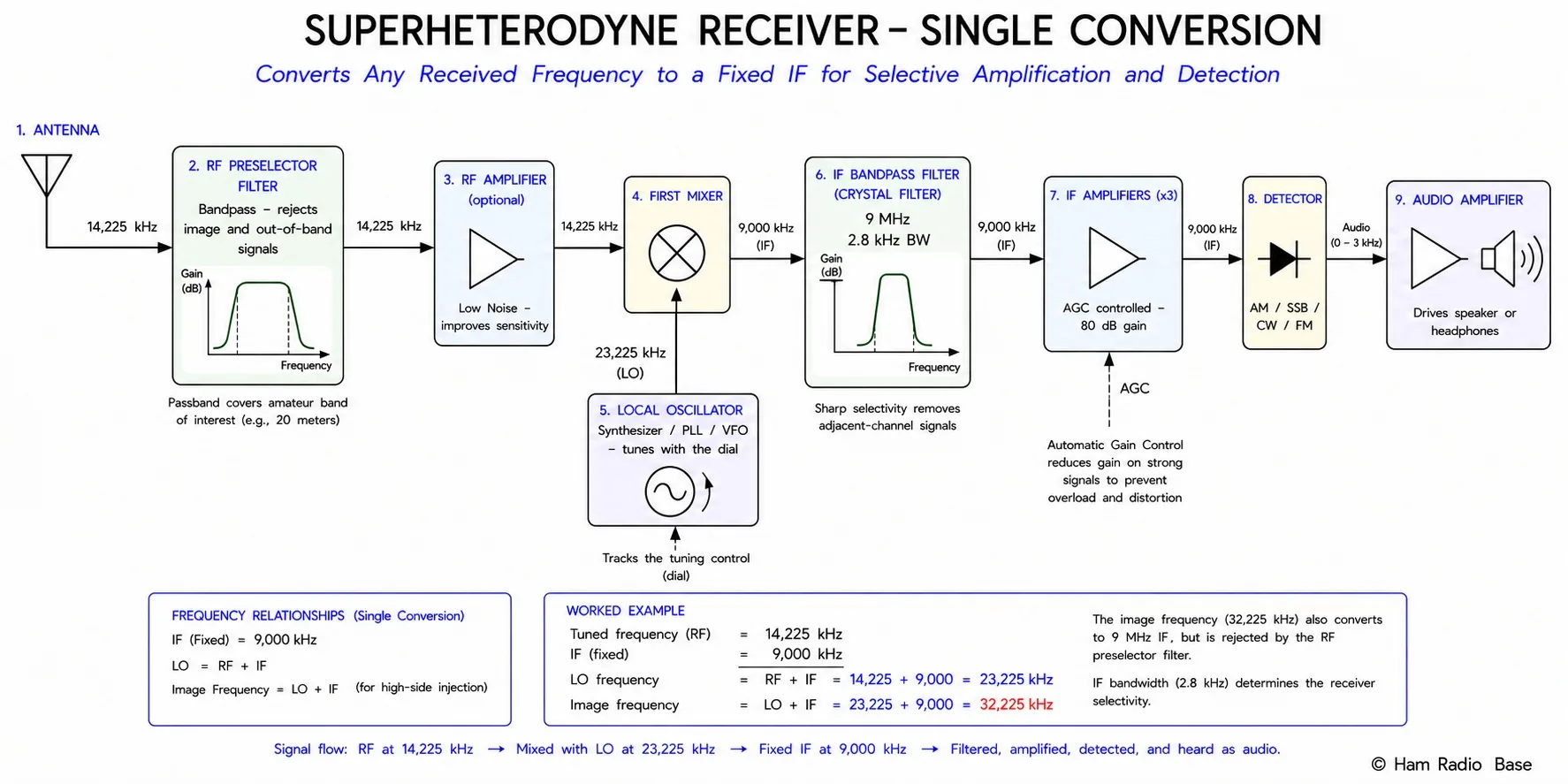
The signal path through a single-conversion superhet:
- Antenna: Receives the RF signal. For HF, a wire or vertical antenna; for VHF/UHF, a Yagi, discone, or whip.
- RF amplifier (preamplifier): Provides low-noise amplification of the desired signal before mixing. Sets the noise figure (NF) of the entire receiver. Optional in some designs — the mixer itself may be the first active stage.
- Preselector filter: A bandpass filter ahead of the mixer that rejects signals at the image frequency (and out-of-band interference). Critical for image rejection.
- Mixer: Multiplies the RF signal by the local oscillator (LO), producing sum and difference products. The IF filter selects the difference product.
- Local oscillator (LO): A variable-frequency oscillator (VFO) or synthesizer that tunes the receiver by shifting the desired signal to the IF. Changed whenever the tuning dial moves.
- IF filter: A fixed-frequency bandpass filter (crystal, ceramic, or mechanical) that provides the receiver's primary selectivity. Bandwidth matches the mode (e.g., 2.4 kHz for SSB, 500 Hz for CW, 15 kHz for WBFM).
- IF amplifier: High-gain amplifier at the fixed IF. Provides most of the receiver's total gain (typically 60–100 dB).
- Detector/demodulator: Recovers the audio from the IF signal (envelope detector for AM, product detector for SSB/CW, discriminator or PLL for FM).
- Audio amplifier: Amplifies the recovered audio to drive a speaker or headphones.
- AGC: Senses the IF signal level and feeds back a control voltage to reduce IF amplifier gain when strong signals are received.
LO Frequency Calculation
The mixer generates output products at fRF ± fLO. For the IF filter to select the signal, one of these products must equal the IF:
High-side injection (LO above RF): fLO = fRF + fIF
Low-side injection (LO below RF): fLO = fRF − fIF
High-side injection is most common — it places the LO above the signal, which is generally more stable and simplifies some circuit designs.
Desired signal: 14.200 MHz (20m USB)
IF: 8.215 MHz (common in modern HF transceivers)
High-side injection: fLO = 14.200 + 8.215 = 22.415 MHz
Low-side injection: fLO = 14.200 − 8.215 = 5.985 MHz
For a 455 kHz IF (AM broadcast radio) receiving 1,000 kHz:
High-side: fLO = 1,000 + 455 = 1,455 kHz
Low-side: fLO = 1,000 − 455 = 545 kHz
The Image Frequency
The image frequency is the critical limitation of any single-conversion superhet. When the mixer multiplies fRF by fLO, it produces the desired difference (fLO − fRF = fIF), but it also produces the same difference from a second RF frequency — the image — on the other side of the LO:
High-side injection: fimage = fRF + 2 × fIF
Low-side injection: fimage = fRF − 2 × fIF
The image frequency is 2×IF away from the desired signal, on the far side of the LO.
fRF = 14.200 MHz, fIF = 8.215 MHz, high-side injection
fLO = 14.200 + 8.215 = 22.415 MHz
fimage = 14.200 + 2 × 8.215 = 14.200 + 16.430 = 30.630 MHz
Any signal at 30.630 MHz entering the mixer will also produce a 8.215 MHz IF output, appearing as interference on the desired 14.200 MHz channel.
For a 455 kHz IF receiving 1,000 kHz (high-side LO = 1,455 kHz):
fimage = 1,000 + 2 × 455 = 1,910 kHz
Image rejection is the ability of the receiver to suppress signals at the image frequency. It is provided primarily by the preselector filter (bandpass filter before the mixer). The preselector must attenuate the image frequency while passing the desired signal — both are 2×IF apart. A higher IF means the image is farther from the desired signal in absolute frequency, making it easier for the preselector to attenuate it. This is why high-performance HF receivers use high first IFs (45–75 MHz or even higher).
Double Conversion
The single-conversion superhet faces a fundamental tradeoff: a high IF provides excellent image rejection but makes it harder to build sharp, narrow IF filters (high-Q filters are harder to build at higher frequencies); a low IF allows excellent selectivity filters but the image is close to the desired signal and hard to reject with a simple preselector.
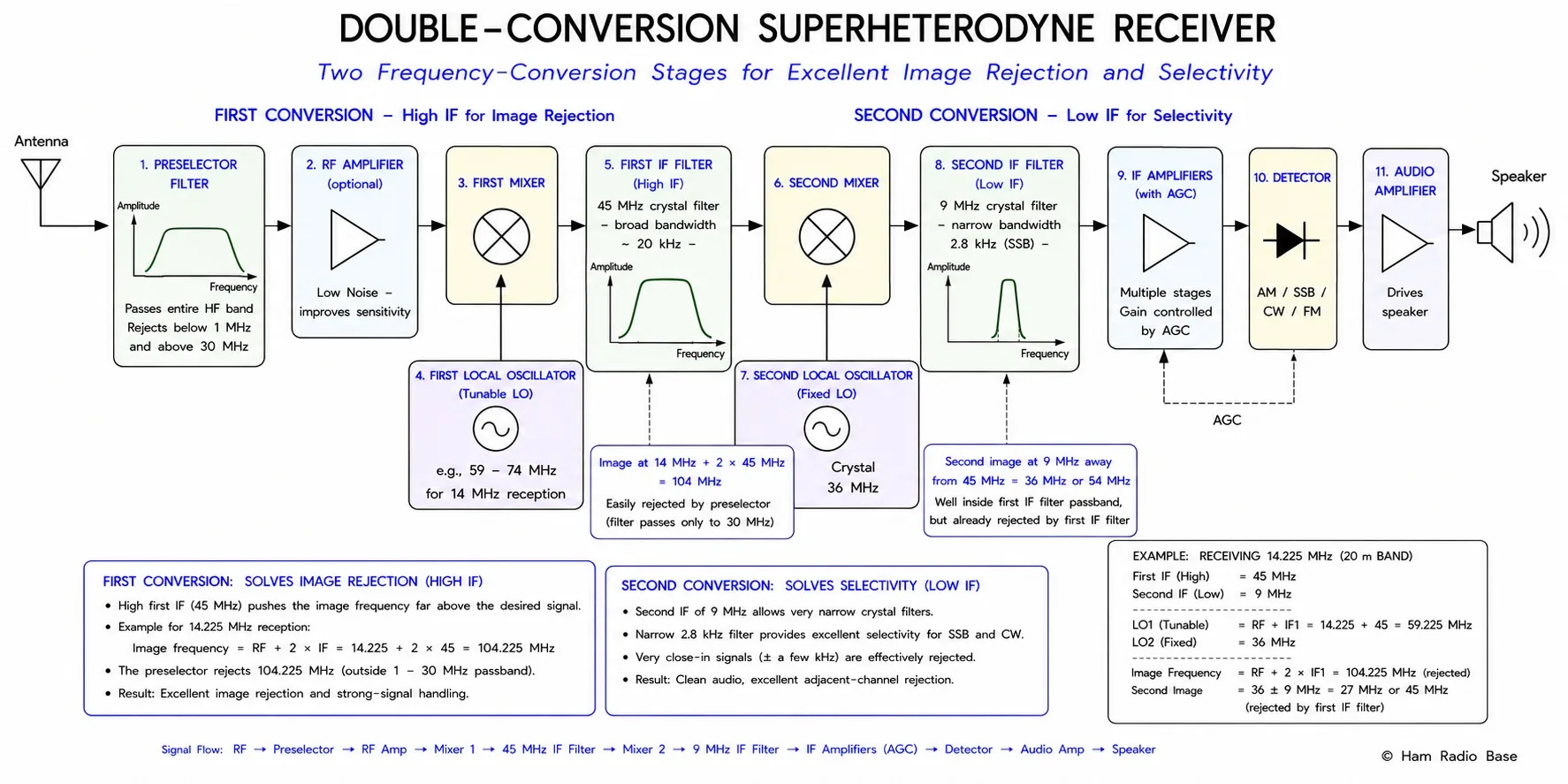
Double conversion resolves this by using two IF stages:
- First IF: High frequency (8–75 MHz) — image is 2×IF1 away; wide preselector filter is sufficient to reject it
- Second IF: Low frequency (455 kHz, 8.215 MHz, or 9 MHz) — sharp crystal or mechanical filters provide channel selectivity
- First LO tunes across the band; second LO is fixed (or nearly fixed)
Incoming RF: 14.200 MHz
First IF: 45.000 MHz (fixed crystal filter, wide)
First LO: 14.200 + 45.000 = 59.200 MHz (tunable VFO or synthesizer)
Image of first conversion: 14.200 + 2×45 = 104.2 MHz — well out of the HF band, easily rejected
Second IF: 455 kHz (crystal or mechanical filter, narrow)
Second LO: 45.000 − 0.455 = 44.545 MHz (fixed or slightly tunable)
Image of second conversion: at the first IF ± 2×455 kHz — rejected by the first IF filter
Automatic Gain Control (AGC)
Radio signals arrive at receivers over a dynamic range of 100 dB or more — a barely detectable signal from a distant station might be 0.1 μV; a nearby station might be 1 V. Without gain control, a strong signal would saturate the IF amplifiers and produce distorted audio, while a weak signal would be inaudible. Automatic gain control (AGC) automatically adjusts receiver gain to maintain a roughly constant audio output level across this wide input range.
AGC operation:
- A detector (usually a simple peak detector or an IF-level sampler) measures the amplitude of the IF signal.
- The DC voltage from the detector is compared to a reference (the desired IF level).
- The difference (error) is amplified and fed back as a control voltage to variable-gain IF amplifier stages.
- When IF level rises (strong signal), the control voltage reduces IF amplifier gain. When level falls (weak signal), gain increases.
- Attack time: How fast AGC responds to a suddenly stronger signal (typically 1–10 ms for voice). Fast attack prevents overload from strong signal bursts.
- Decay time: How fast AGC releases when a strong signal disappears (typically 100 ms to 3 seconds). Slow decay prevents noise bursts between words in voice.
- For CW: fast attack and medium decay. For SSB voice: medium attack (avoids chopping word beginnings), medium decay. For AM: slow attack and decay.
The Superhet in Amateur Radio
Virtually all modern amateur HF transceivers use double or triple conversion superheterodyne architectures. The first IF is typically in the range of 40–75 MHz (for excellent image rejection across the HF spectrum), the second IF is often in the range of 8–10 MHz (for SSB crystal filter selection), and many designs add a third conversion to a lower IF (455 kHz, 8.215 kHz) for narrow CW filters.
Software-defined radio (SDR) transceivers — now common in amateur use — often use a single high-IF conversion followed by ADC (analog-to-digital conversion) directly at the IF, with all further filtering, demodulation, and audio processing in DSP software. This "SDR superhet" retains the image-rejection advantage of a high first IF while replacing all fixed-IF hardware with software-configurable DSP chains. The Icom IC-7610, Yaesu FTDX10, and Elecraft K4 are examples of high-performance SDR-based amateur HF transceivers.
Frequently Asked Questions
Why doesn't the superhet receiver use the sum frequency output of the mixer instead of the difference?
Both the sum (fRF + fLO) and difference (|fRF − fLO|) products are present at the mixer output. The IF filter selects whichever product equals the desired IF. In principle you could use the sum product — but the sum of an RF frequency and an LO frequency (both in the MHz range) would be in the hundreds of MHz or GHz range, far above the RF input frequency. Building sharp, narrow crystal filters at such high frequencies is expensive and difficult. The difference product (typically 455 kHz to 45 MHz) places the IF at a frequency where excellent crystal and mechanical filters are available at reasonable cost. This is why the difference is universally chosen as the IF product.
What happens if the receiver is tuned to the image frequency instead of the desired signal?
If a signal at the image frequency is present and the preselector filter does not reject it, the receiver cannot distinguish it from the desired signal — both produce the same IF output. The image signal appears in the audio as if it were a legitimate station on the tuned frequency. On HF, this can cause a distant station's signal to appear as interference on a completely different frequency. The remedy is adequate image rejection: a high IF places the image far from the desired signal, and a sharp preselector (bandpass filter before the mixer) attenuates the image before it reaches the mixer. Image rejection is typically specified in dB — a good HF receiver has 70–90 dB image rejection.
What is LO radiation and why is it a problem?
The local oscillator in a superhet generates a continuous RF signal at fLO. If this signal leaks back through the mixer to the antenna (via the RF amplifier path or through direct radiation), it can interfere with other receivers nearby — your neighbors may hear your LO as a carrier on their receivers. LO radiation is suppressed by: (1) adequate shielding of the LO and mixer circuit; (2) sufficient reverse isolation in the RF amplifier (the amplifier should attenuate signals passing backward through it); (3) a preselector filter with reverse attenuation that blocks the LO frequency; and (4) good RF engineering practice in the PCB layout (avoiding coupling paths between LO and the antenna lead). FCC rules limit spurious emissions from receivers, which includes LO radiation.
What is the purpose of the preselector filter?
The preselector is a bandpass or low-pass filter placed between the antenna and the first mixer. Its primary jobs are: (1) attenuating signals at the image frequency before they reach the mixer (image rejection); (2) attenuating strong out-of-band signals that might cause intermodulation in the mixer (strong-signal performance); (3) reducing the LO radiation from reaching the antenna; and (4) providing some protection against static discharge and lightning-induced transients on the antenna. In simple AM broadcast radios, the preselector is a single tuned circuit (the antenna coil resonated by the tuning capacitor). In high-performance HF receivers, the preselector is a switched or continuously-tuned bandpass filter with 60–80 dB image attenuation.
What is the difference between a receiver's sensitivity and selectivity?
Sensitivity is the minimum signal level the receiver can detect at a specified signal-to-noise ratio — it describes how weak a signal the receiver can copy. It is measured as minimum discernible signal (MDS) in dBm, or as noise figure (NF) in dB. Selectivity is the receiver's ability to reject signals on adjacent frequencies while receiving the desired signal — it describes how well the receiver separates closely-spaced signals. Selectivity is determined primarily by the IF filter bandwidth and shape factor. A receiver can be highly sensitive (low noise figure) but poor at selectivity (wide IF filter), or highly selective but not very sensitive. For amateur HF operation, both matter: sensitivity for weak-signal DX work, selectivity for crowded band conditions.
Test Your Knowledge
Answer the questions below to check your understanding of the superheterodyne receiver.