Phase Modulation
Phase modulation (PM) is the sibling of frequency modulation — in PM, it is the phase of the carrier that shifts in proportion to the instantaneous amplitude of the modulating signal rather than the carrier's frequency. On the surface PM and FM sound identical: both produce a constant-amplitude signal with a varying instantaneous frequency. The difference lies in the mathematical relationship between modulating frequency and the resulting phase or frequency swing, and that difference has profound consequences for sidebands, bandwidth, and system design. PM is the foundation of every modern digital radio system — BPSK, QPSK, and their derivatives are all forms of phase modulation — yet it also appeared in early broadcast radio through Edwin Armstrong's indirect FM transmitter. This lesson builds PM from the ground up: the equation, the deviation, the PM-vs-FM comparison, Armstrong's indirect FM, and the family of digital PSK modulation schemes used across HF digital modes and satellite links.
The PM Equation
A PM signal is described mathematically as:
v(t) = Vc · sin[2πfct + Δφ · m(t)]
- Vc — carrier amplitude (constant)
- fc — carrier frequency (constant)
- Δφ — peak phase deviation in radians
- m(t) — normalized modulating signal (−1 to +1)
The entire information payload lives inside the square bracket, in the phase term Δφ·m(t). When m(t) = +1 (positive peak of the audio tone), the carrier phase advances by Δφ radians ahead of an unmodulated carrier. When m(t) = −1, the phase retards by Δφ radians. The amplitude Vc never changes — PM is a constant-envelope mode, just like FM.
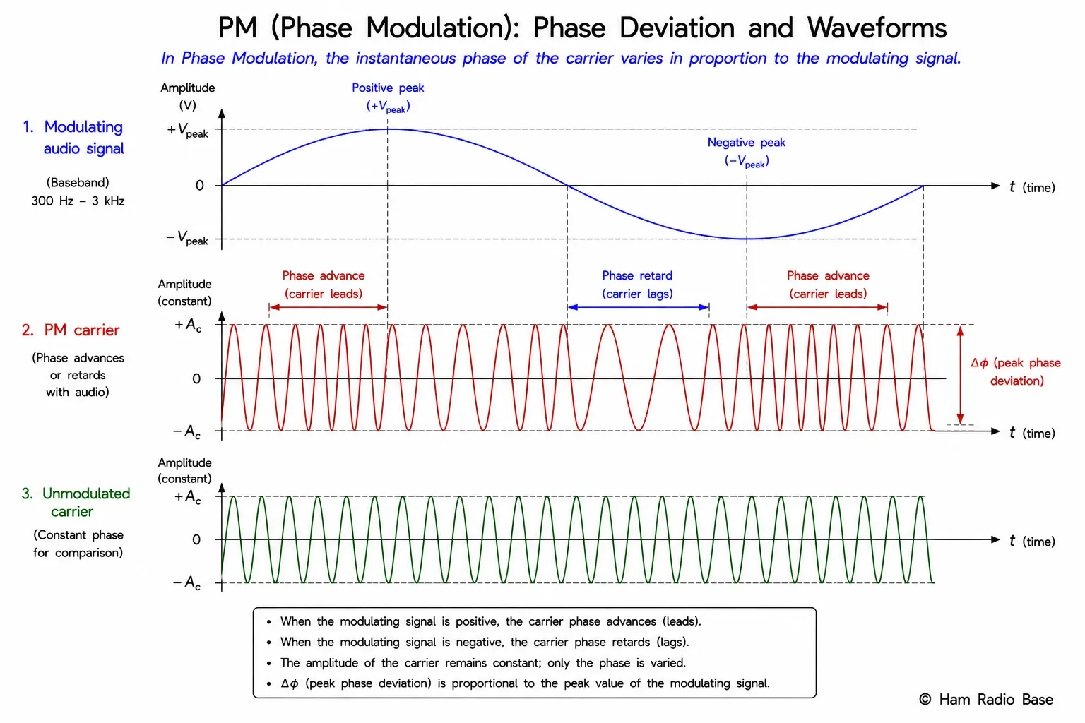
The instantaneous frequency of a PM signal is not constant even though no deliberate frequency modulation is applied. Because phase is the integral of frequency, a changing phase implies a changing instantaneous frequency:
finst(t) = fc + Δφ · fm · cos(2πfmt)
Notice that fm — the modulating frequency — appears as a multiplier of the frequency swing. This is the crucial difference from FM, explored in detail below.
Phase Deviation in Radians
Phase deviation Δφ is measured in radians (rad). One radian is approximately 57.3°; a full cycle is 2π ≈ 6.28 rad. A PM transmitter with Δφ = 1 rad shifts the carrier phase by about 57° at the peak of the modulating signal. A BPSK signal (discussed below) uses Δφ = π rad = 180°.
A PM transmitter has Δφ = 2.5 rad. With a 1 kHz tone at full modulation:
- Peak phase advance: +2.5 rad = +143°
- Peak phase retard: −2.5 rad = −143°
- Effective frequency deviation: Δf = Δφ × fm = 2.5 × 1,000 = 2,500 Hz
This frequency-proportional deviation is the PM signature — it does not occur in FM.
The PM modulation index β used for sideband analysis equals Δφ (in radians) when the modulating signal is a single tone. This makes PM and FM sidebands mathematically identical when β is the same — Bessel function analysis applies to both.
PM vs FM: Key Differences
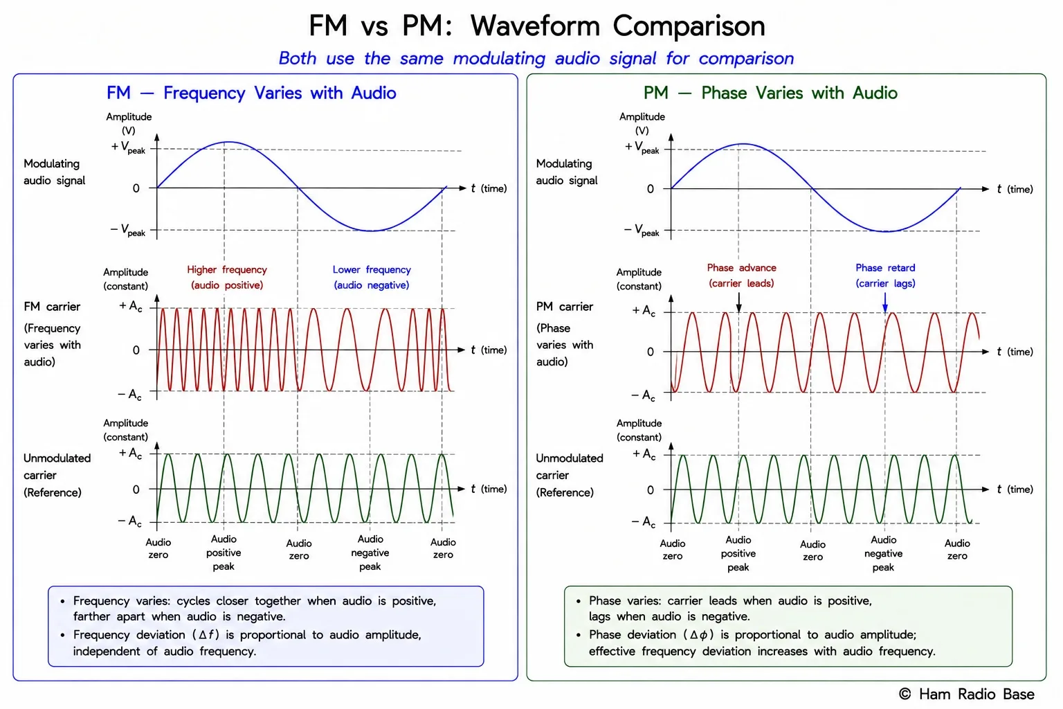
The defining distinction between PM and FM is how each responds to a change in the modulating frequency while keeping the modulating amplitude constant:
| Property | FM | PM |
|---|---|---|
| What varies with modulation amplitude | Frequency deviation (Δf) | Phase deviation (Δφ) |
| Effect of doubling modulating frequency (same amplitude) | Δf stays the same; modulation index β halves | Δφ stays the same; frequency deviation doubles |
| Effect of doubling modulating amplitude (same frequency) | Δf doubles; β doubles | Δφ doubles; Δf doubles |
| Demodulation circuit | FM discriminator (Foster-Seeley, ratio detector, PLL) | Phase comparator or FM discriminator preceded by differentiator |
| Noise spectrum at output | Noise rises with frequency (triangular noise spectrum) | Flat noise spectrum (PM demodulator output) |
The FM receiver's triangular noise characteristic arises because FM discriminator output noise power is proportional to f². PM demodulators produce flat noise because phase noise at the demodulator input maps directly to phase-error output without the f² weighting. For voice, neither format is clearly superior; the pre-emphasis curves used in FM broadcasting partially compensate for the triangular noise by boosting high audio frequencies before transmission.
Armstrong Indirect FM
Edwin Armstrong — the inventor of FM radio — built his first FM transmitters using phase modulation, not direct frequency modulation. The reason: stable, accurate direct FM requires a voltage-controlled oscillator (VCO) whose frequency must be locked to a reference despite the modulation. In 1936, practical AFC circuits were crude and unreliable. Armstrong found he could generate a crystal-stable carrier, phase-modulate it at a very small deviation, and then frequency-multiply the signal to expand the deviation to the target value — all while maintaining the frequency accuracy of the crystal reference.
The indirect FM (Armstrong) exciter process:
- Generate a stable carrier from a crystal oscillator at a low frequency (e.g., 200 kHz).
- Apply narrowband phase modulation — the audio is first integrated (passed through a 1/f network) to convert from PM to an equivalent FM characteristic before modulation, then the phase modulator applies a very small Δφ (fraction of a radian).
- Apply frequency multipliers (e.g., ×72) to raise the carrier to the desired frequency and simultaneously expand the deviation by the same factor.
- Heterodyne (mix) to the final carrier frequency as needed to reach the transmit channel.
Crystal: 200 kHz. Phase modulator applies Δφ = 0.01 rad. The audio passes through an integrator (1/f network) before the phase modulator, converting the effective response to FM-like deviation. Frequency multiplier chain: ×72 raises 200 kHz to 14.4 MHz and expands effective deviation by 72. A mixer shifts to the final broadcast frequency. The result: a fully stable FM signal whose frequency accuracy is set by the crystal, not by a drifting VCO.
The integration step before the phase modulator is critical. Without it, a PM transmitter's audio response would emphasize high frequencies (because Δf = Δφ×fm). Integrating the audio first provides a 6 dB/octave frequency rolloff that exactly cancels the PM's natural 6 dB/octave rise, producing flat audio response — identical to FM. The Armstrong exciter is therefore an indirect FM generator even though its modulation mechanism is phase-based.
BPSK and QPSK
Binary phase-shift keying (BPSK) and quadrature phase-shift keying (QPSK) are the simplest members of the PSK family — they are just PM signals where the modulating "signal" is a digital data stream rather than an analog voice waveform.
BPSK
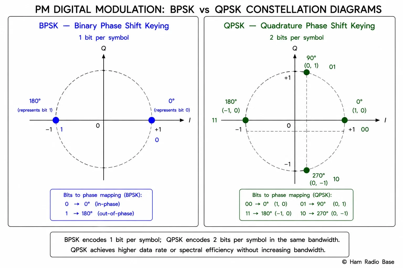
In BPSK, the carrier takes one of exactly two phase states: 0° and 180° (or equivalently, Δφ = 0 and Δφ = π radians). A logic "1" maps to 0° and a logic "0" maps to 180°, or vice versa depending on the standard. The phase shift is typically abrupt at each bit boundary, producing a waveform where the carrier appears to flip polarity at transitions.
The abrupt phase transitions in BPSK (and the resulting spectral splatter) are commonly managed by pulse shaping — raised-cosine or root-raised-cosine filters that smooth the transitions and contain the spectrum. PSK31, the popular HF digital mode used by amateur radio operators, uses differential BPSK (DBPSK) with raised-cosine shaping and operates in a bandwidth of about 31 Hz.
QPSK
Quadrature phase-shift keying uses four phase states: 0°, 90°, 180°, and 270°. Two bits are encoded per symbol (00 → 0°, 01 → 90°, 11 → 180°, 10 → 270° in the standard Gray-coded mapping). This doubles the spectral efficiency compared to BPSK: 2 bits per symbol in the same bandwidth.
Higher-order PSK variants (8-PSK uses 8 states/3 bits per symbol; 16-PSK uses 16 states/4 bits per symbol) exist but become increasingly sensitive to phase noise and amplitude impairments. Satellite and microwave links commonly use QPSK or 8-PSK for the balance of spectral efficiency and noise margin.
Constellation Diagrams
A constellation diagram plots the in-phase (I) component of a signal on the horizontal axis and the quadrature (Q) component on the vertical axis at each symbol instant. Every modulation scheme maps to a characteristic pattern of dots — the "constellation."
For a carrier with phase θ and amplitude A, the I and Q components are:
I = A · cos(θ)
Q = A · sin(θ)
- BPSK: Two points at (A, 0) and (−A, 0). Both lie on the I-axis. Q = 0 always.
- QPSK: Four points at (±A/√2, ±A/√2), arranged at 45°, 135°, 225°, 315°.
- AM/DSB-SC: Points along the I-axis at varying amplitudes — a line, not a cluster.
Noise and phase error cause the received points to spread into clouds around the ideal positions. When two clouds overlap, the receiver makes bit errors. The minimum Euclidean distance between adjacent constellation points determines the bit-error-rate (BER) performance: larger separation means better noise immunity for a given signal power.
The constellation is a snapshot; an oscilloscope in I-Q (vector) mode shows the trajectory the signal traces as it moves between symbol points. For BPSK the trajectory passes through zero (the origin) at each polarity reversal — this momentary zero-crossing creates the wide spectrum of unfiltered BPSK. Pulse shaping forces the trajectory to avoid or skirt the origin, containing the spectrum without increasing average power.
The Costas Loop
PSK signals — especially BPSK — are often transmitted with suppressed carrier: the carrier component is eliminated and only the sidebands are sent, just as in DSB-SC AM. This saves power (no energy is wasted on a carrier that carries no information), but it creates a demodulation problem: the receiver must regenerate the reference carrier in exact phase synchrony with the transmitter's carrier to correctly decode the data. Inserting a pilot tone is wasteful; the Costas loop solves the problem with no pilot at all.
The Costas loop is a phase-locked loop topology that exploits the symmetry of the BPSK signal to extract a carrier reference. The received signal is split and multiplied by both a local oscillator (I channel) and the same LO shifted 90° (Q channel). The Q-channel product after low-pass filtering contains a term proportional to sin(Δθ) — the phase error between the local reference and the true carrier. This error signal drives a voltage-controlled oscillator (VCO) that closes the loop, locking the LO to the suppressed carrier frequency and phase.
- Split received signal → multiply by LO (I arm) and LO shifted 90° (Q arm)
- Low-pass filter both arms → recover baseband I and Q
- Multiply I × Q → produces phase-error signal
- Filter error → drive VCO → lock LO to suppressed carrier
- I-arm output after lock: clean BPSK baseband data bits
The Costas loop has a 180° phase ambiguity: it will lock equally well to 0° or 180° because those are indistinguishable at suppressed-carrier BPSK. Differential encoding (DBPSK) resolves this — data is encoded as the change from one symbol to the next rather than the absolute symbol value, so a 180° carrier ambiguity causes no data errors.
PM in Amateur Radio
Direct phase modulation has limited use in amateur voice communication — most "FM" handheld radios are actually narrowband PM (NBPM) units. The audio processing in a typical handheld applies a high-pass pre-emphasis before the phase modulator. Because PM deviation rises with frequency (Δf = Δφ×fm), flatter audio response from the modulator would overdeviate on high-pitched speech. The built-in pre-emphasis compensates for the channel and the PM characteristic together — on a properly calibrated FM channel, the received audio sounds natural even though the transmitter uses PM internally. Many commercial FM-channel handheld radios labeled "FM" are technically PM transmitters.
PSK digital modes on HF — PSK31, PSK63, WSPR (which uses 4-FSK but is related) — leverage phase modulation for remarkably narrow bandwidth. PSK31 occupies about 31 Hz, less than 1% of the 3 kHz SSB voice bandwidth, and achieves contacts at very low power across intercontinental paths. The mode uses differential BPSK with shaped transitions so the transmitted spectrum falls off steeply outside the 31 Hz passband.
Satellite uplinks and downlinks in the amateur service (AO-7, FO-29, and others) use BPSK or QPSK telemetry and, increasingly, QPSK for the linear transponders. Understanding constellation diagrams and Costas loop recovery is directly applicable to building or operating amateur satellite ground stations.
Frequently Asked Questions
What is the practical difference between FM and PM for a voice signal?
For a single-tone audio signal both produce identical waveforms if the modulation index is the same. The difference appears with a multi-frequency audio signal: an FM transmitter keeps the same peak frequency deviation regardless of which audio frequencies are present, while a PM transmitter's peak frequency deviation increases with audio frequency. FM systems apply pre-emphasis (6 dB/octave boost) before the FM modulator and de-emphasis after the FM demodulator to improve high-frequency SNR. PM systems have a complementary characteristic built in. In practice most narrowband handheld "FM" radios actually use PM internally with appropriate audio processing to sound correct on an FM channel.
Why does PSK31 use differential BPSK (DBPSK) rather than absolute BPSK?
The Costas loop and most practical carrier recovery circuits have a 180° phase ambiguity — they lock equally well to the true carrier phase or a phase 180° opposite. With absolute BPSK, a 180° lock error would invert every bit, producing all errors. Differential encoding removes this ambiguity: each bit is encoded as whether the phase changed (0° → bit 0, 180° → bit 1) rather than as the absolute phase value. A 180° carrier ambiguity causes no data errors because every "change" and "no change" decision is still correct. DBPSK costs about 3 dB in sensitivity compared to coherent BPSK but the practical convenience of carrier-ambiguity immunity far outweighs this penalty on HF.
What does the I-Q representation physically mean?
I (in-phase) and Q (quadrature) are two orthogonal components of a sinusoidal signal. Any sinusoid of fixed frequency can be uniquely described by its I and Q amplitudes: the signal equals I·cos(2πfct) − Q·sin(2πfct). I and Q are real baseband values — they can be positive or negative, they can be computed slowly in a DSP chip, and they carry the full information of any amplitude- or phase-modulated RF signal. A software-defined radio (SDR) receiver produces I and Q streams at baseband; all further demodulation (AM, FM, SSB, BPSK, QPSK) is software. Plotting I vs Q at symbol instants gives the constellation diagram, which makes the modulation format immediately visible as a pattern of dots.
Can an FM receiver decode PSK31?
Not directly. PSK31 is a phase-modulated signal received via SSB (USB) on HF — the audio output of the SSB receiver is fed into a computer's sound card and decoded by software such as Fldigi. An FM receiver outputs audio proportional to frequency deviation, which cannot reconstruct BPSK phase transitions. To decode PSK31 you need an HF transceiver in USB mode, not FM mode. The SSB demodulator preserves the baseband I component of the signal (Q is discarded in a simple SSB detector); the software then uses a Costas loop or decision-directed phase tracking algorithm to recover the carrier reference and decode bits.
What is the difference between baud and bit rate for QPSK?
Baud (symbol rate) is the number of symbol changes per second. Bit rate is the number of bits delivered per second. For BPSK, baud and bit rate are equal because each symbol carries 1 bit. For QPSK each symbol carries 2 bits, so bit rate = 2 × baud. A QPSK signal at 2,400 baud delivers 4,800 bits/s. The occupied bandwidth is determined by the baud rate (symbol rate), not the bit rate — so QPSK delivers twice the bits in the same bandwidth as BPSK at the same symbol rate. This is why higher-order PSK and QAM are preferred on spectrum-constrained links: more bits per baud, same channel width.
Test Your Knowledge
Answer the questions below to check your understanding of phase modulation.