CW and On-Off Keying
Continuous wave (CW) is the oldest form of radio communication and, in many respects, still the most efficient. A CW transmitter does nothing more than switch a carrier on and off in a pattern of dots and dashes — Morse code. This is on-off keying (OOK): the simplest possible form of modulation, requiring no complex circuitry, surviving under conditions that defeat every other mode, and occupying the narrowest bandwidth of any practical communication system. Yet behind this apparent simplicity lies surprisingly rich engineering: the shape of each keying transition determines whether the signal occupies 100 Hz or 10 kHz; the beat-frequency oscillator in the receiver is a miniature heterodyne mixer; and the noise performance of a well-designed CW system outperforms SSB and FM by margins that make it the DX operator's first choice. This lesson covers all of it — from the physics of OOK to the design of the CW receiver.
On-Off Keying Fundamentals
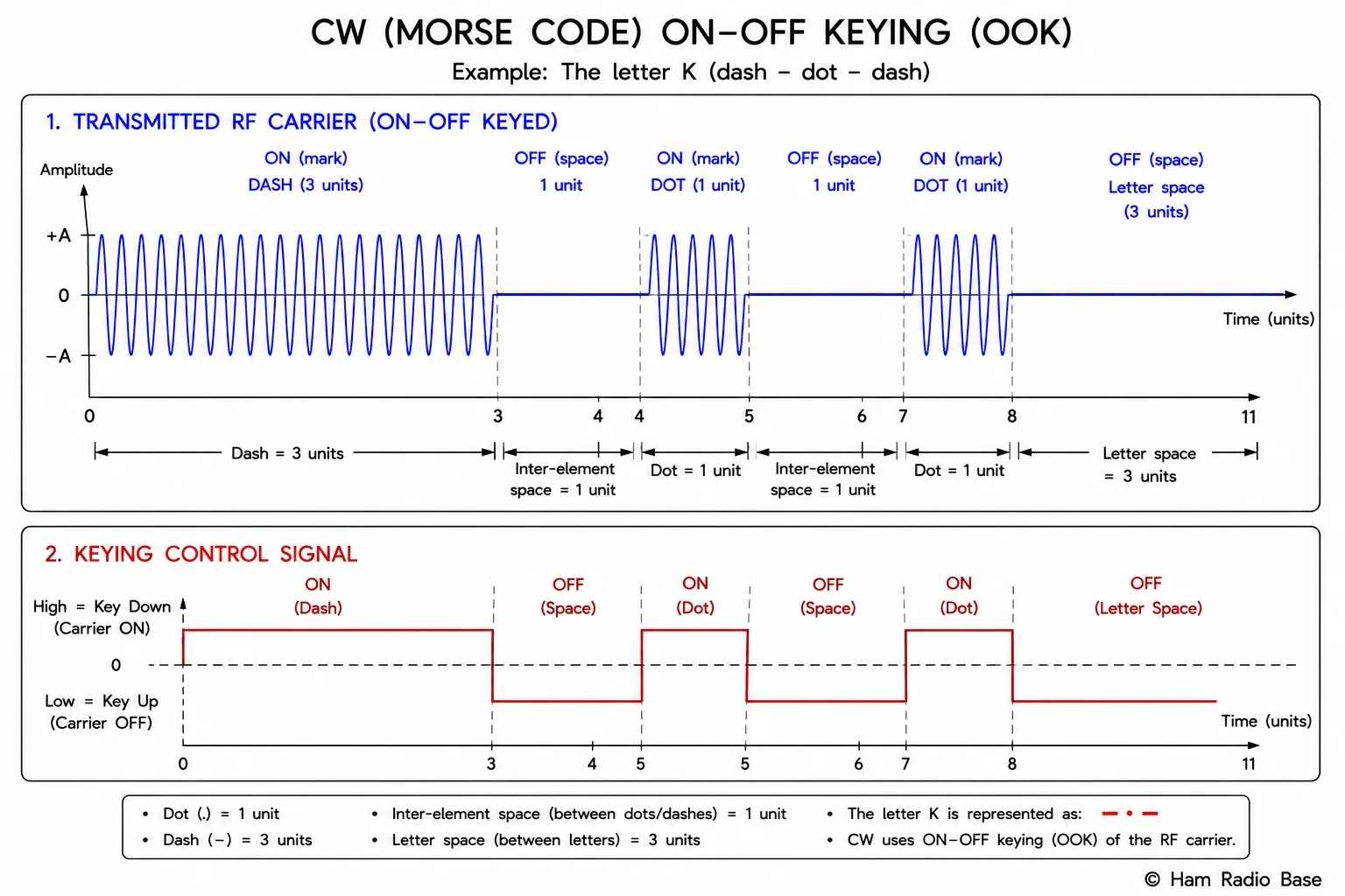
On-off keying is the simplest digital modulation scheme: the transmitter is either fully on (key down, carrier present) or fully off (key up, no carrier). In Morse code terms, a dit (dot) is a short key-down interval followed by an equal key-up interval; a dah (dash) is three times as long. The ratio of key-down time to key-down plus key-up time is the duty cycle. At 50% duty cycle (equal on and off) the average power is half the peak power.
v(t) = A · k(t) · cos(2πfct)
where k(t) = 1 (key down) or k(t) = 0 (key up)
In the frequency domain, OOK is a double-sideband AM signal with 100% modulation depth and a suppressed (zero-amplitude) carrier during key-up periods. Because the modulating "signal" k(t) is a baseband on-off pattern rather than a sine wave, the sidebands are not simple tones — they reflect the Fourier spectrum of the keying waveform, which depends critically on the shape of the transitions.
The OOK Waveform
The time-domain OOK signal for a single keyed element is a rectangular pulse of RF carrier with duration T. The Fourier transform of a rectangular pulse is a sinc function: sinc(f·T) = sin(πf·T) / (πf·T). The bandwidth of the sinc main lobe is approximately 2/T — twice the reciprocal of the pulse duration. Faster keying (shorter T) means wider main lobe, hence wider bandwidth.
For Morse code, the shortest element is a dit. At a keying speed of N words per minute (WPM), the standard dit duration is:
Tdit = 1.2 / N seconds (N in WPM)
Approximate occupied bandwidth:
BW ≈ 4 / Tdit = 4 × N / 1.2 ≈ 3.3 × N Hz
Tdit = 1.2 / 25 = 0.048 s (48 ms)
Approximate bandwidth: BW ≈ 3.3 × 25 = 83 Hz
At 50 WPM: BW ≈ 3.3 × 50 = 165 Hz
Compare: SSB voice occupies about 2,700 Hz. CW at 25 WPM occupies less than 3% of that.
Hard vs Soft Keying
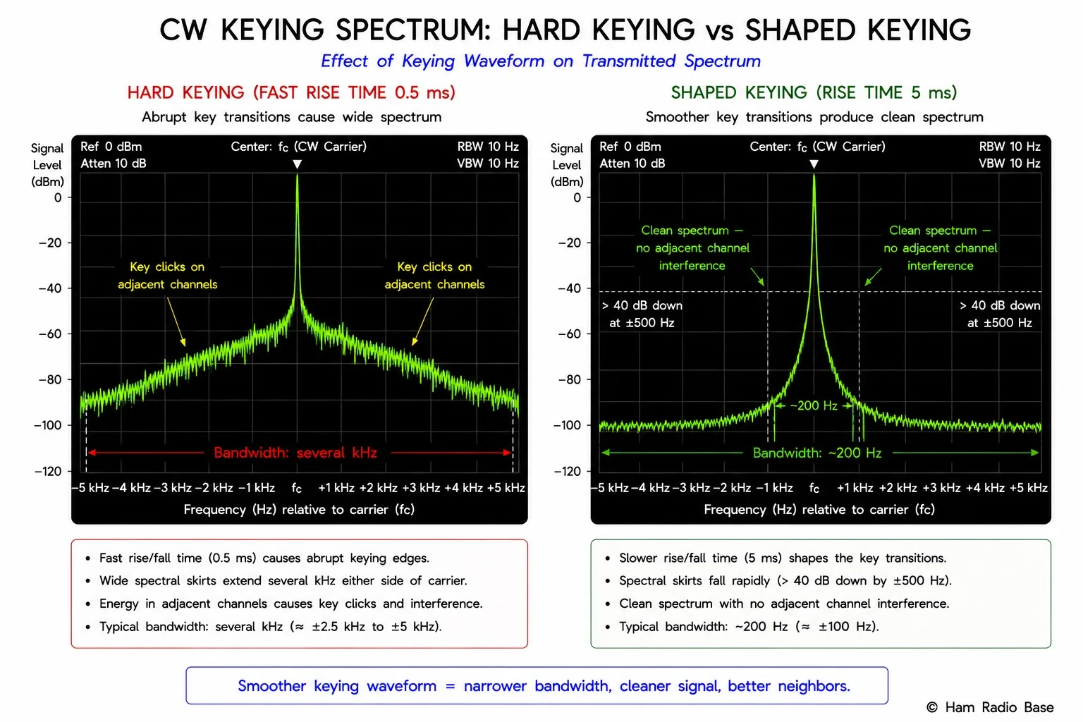
Hard keying switches the carrier on and off instantaneously — the rise and fall times are essentially zero. A step change in amplitude contains energy at all frequencies: the Fourier transform of a unit step is 1/(j2πf), which falls off only as 1/f. This produces sidebands that extend far from the carrier, potentially interfering with stations many kHz away.
Soft keying (shaped keying) shapes the envelope of each transition with a raised-cosine, Gaussian, or exponential curve. The rise time Tr (10% to 90% amplitude) acts as a low-pass filter on the keying waveform: sidebands at frequencies greater than 1/Tr are heavily attenuated. The ITU and amateur regulations specify maximum rise and fall times for CW transmitters to limit spectral occupancy.
- Rise time: 5–10 ms (faster rise = wider spectrum)
- Fall time: 5–10 ms (matched to rise for symmetric shaped envelope)
- Rise/fall shaping: raised-cosine or exponential preferred over linear
- Minimum element duration must be > 2× rise time to avoid envelope distortion
Key Clicks and Spectral Splatter
Key clicks are the audible pops heard on nearby receivers when a CW transmitter uses insufficiently shaped keying. They result from the broadband energy of the fast transitions — the abrupt onset and cessation of the carrier creates sidebands that can extend tens of kHz from the carrier frequency, splattering across adjacent channels and causing interference to stations far from the CW frequency.
The mechanism: a perfectly rectangular keying pulse has energy at all harmonics of the keying rate, falling off at 6 dB/octave (20 dB/decade). A shaped (cosine-ramped) pulse's energy falls off much faster — at 40 dB/decade or more — because the smooth transitions eliminate the high-frequency Fourier components. The click heard at the receiver corresponds to the impulsive (wideband) component of the transmitted spectrum that passes through the receiver's IF filter and appears as a brief broadband burst at the speaker.
Click suppression circuits in transmitters typically use a relay-driver integrated circuit or a transistor circuit that ramps a control voltage slowly, which in turn controls the drive level to the PA through a variable-gain stage. Full-break-in (QSK) operation — where the transmitter's TR switching must occur between dits at high speed — makes click suppression more challenging because the envelope shaping must complete within the inter-element gap.
CW Bandwidth and Keying Speed
The ITU definition of necessary bandwidth for CW is:
Bn = B × K × N
where B = bandwidth efficiency factor (typically 1 for CW), K = shaping factor (≈ 1.25 for ITU), N = keying speed in Baud (symbols/s)
Practical approximation: BW (Hz) ≈ 5 × WPM for well-shaped CW
| Speed (WPM) | Dit Duration (ms) | Approx. Bandwidth (Hz) | Typical IF Filter |
|---|---|---|---|
| 5 WPM (beginner) | 240 ms | ≈ 25 Hz | 500 Hz (any CW filter) |
| 15 WPM (novice/tech) | 80 ms | ≈ 75 Hz | 500 Hz |
| 25 WPM (general) | 48 ms | ≈ 125 Hz | 500 Hz or 250 Hz |
| 40 WPM (contest) | 30 ms | ≈ 200 Hz | 250 Hz |
A 500 Hz CW IF filter passes any signal that fits within ±250 Hz of center — sufficient for keying speeds up to about 100 WPM. Narrower filters (250 Hz, 100 Hz) reduce noise bandwidth and improve sensitivity for slow to moderate speed CW at the cost of slightly ringing audio on fast code.
The Beat-Frequency Oscillator
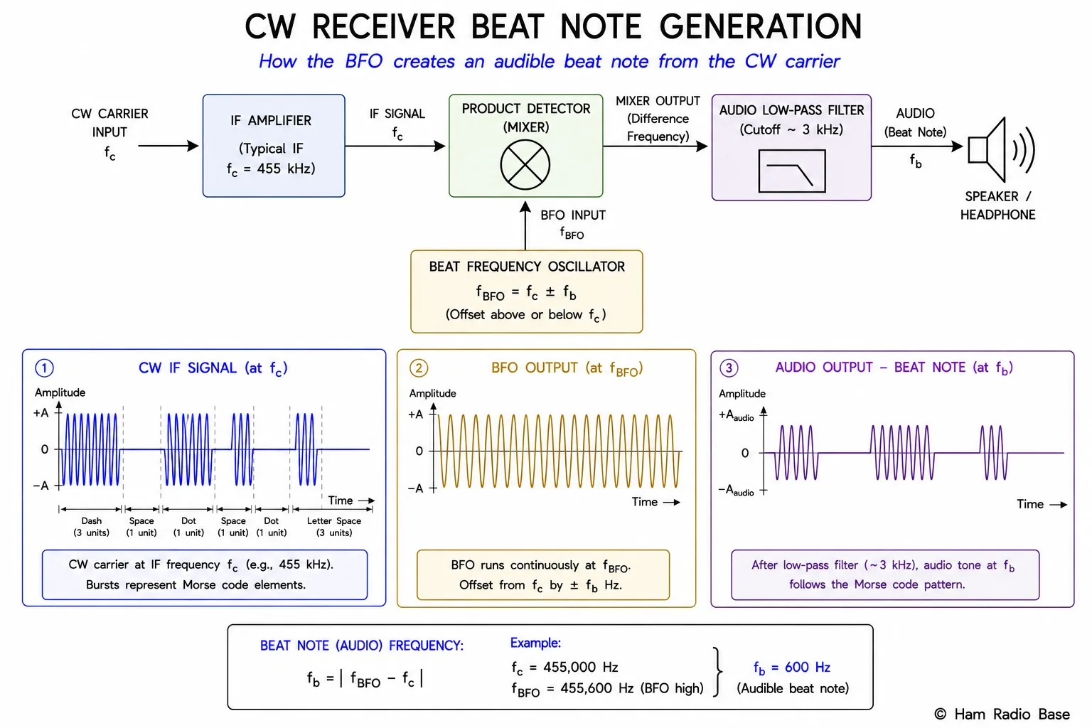
A CW signal at the receiver's IF output is a pure carrier — a single frequency with no audio content. To make it audible, the receiver generates a second signal very close to the IF frequency using a beat-frequency oscillator (BFO). The BFO signal mixes with the CW carrier in a product detector or simple diode detector, producing a beat note at the difference frequency.
fbeat = |fBFO − fIF|
Example: IF = 455 kHz, BFO = 454.4 kHz
fbeat = |454,400 − 455,000| = 600 Hz
The operator adjusts the BFO frequency (or the VFO) to select the pitch of the received tone. A 600 Hz pitch is common — it sits in the center of telephone-quality audio bandwidth and matches the peak sensitivity of the human ear for tone discrimination. Adjusting the receiver's main tuning knob effectively changes the IF frequency and thus the beat note pitch: tuning slightly higher raises the pitch, tuning lower lowers it, until the desired station's CW signal is at the preferred tone.
The BFO is also what enables SSB reception in an AM/CW receiver — the SSB lesson covers this in detail. For CW specifically, the BFO offset from the IF center frequency determines which sideband of the CW signal contributes to the beat note. Because CW is a pure carrier (no sidebands during key-down), there is no distinction between upper and lower BFO offset for a pure carrier, but the choice of BFO side matters when using narrow filters that have asymmetric passbands.
CW Receiver Design
A CW receiver is functionally a superheterodyne receiver (covered in the superheterodyne lesson) optimized for narrow-bandwidth single-tone signals. Key design parameters:
| Parameter | Typical Value | Effect |
|---|---|---|
| IF bandwidth | 250–500 Hz | Narrower = less noise, better adjacent-channel rejection, more ringing on fast code |
| IF filter type | Crystal ladder or DSP | Crystal filters: low cost, fixed; DSP: adjustable width and center frequency |
| BFO offset | 400–800 Hz from IF center | Sets received pitch; 600 Hz is standard practice |
| AGC time constant | Long (500 ms or off) | Short AGC pumps on dits; most CW operators prefer manual RF gain or slow AGC |
| Noise blanker | Optional | Blanks impulse noise (ignition, power-line) that would otherwise mask weak CW |
Modern software-defined radios implement CW IF filtering in DSP, allowing real-time adjustment of filter bandwidth, center frequency, and shape factor during a QSO. The operator can shift the passband to place the desired signal exactly in the filter center even after tuning, compensating for drift or crowded band conditions.
CW in Amateur Radio
CW occupies dedicated sub-bands at the lower edge of most amateur HF allocations. The FCC Part 97 rules no longer require CW proficiency for any US license class (the requirement was eliminated in 2007), but CW remains popular because of its propagation advantages — a CW signal can be copied by ear at signal levels 10–15 dB below the threshold for intelligible SSB, and automatic decoders (using Fast Fourier Transform or Goertzel tone detection) can work even weaker signals. This makes CW the mode of choice for low-power (QRP) DX operation, field expeditions, and contest pile-ups where spectrum efficiency matters.
Electronic keyers generate Iambic (squeeze) keying from dual-lever paddles, producing perfectly timed dits and dahs at rates far beyond hand-key capability. Contest operators routinely exchange contacts at 35–40 WPM using a combination of electronic keyer and keyboard macros. Full-break-in (QSK) operation — where the transmitter fully releases between each dit, allowing the operator to hear between transmitted elements — requires TR switching on the order of milliseconds, achieved with PIN-diode antenna switching or fast vacuum-relay designs.
Frequently Asked Questions
Why is CW so much more efficient than SSB or FM?
CW occupies a bandwidth of roughly 25–200 Hz depending on keying speed, compared to 2,700 Hz for SSB and 16 kHz for WBFM. All available transmitter power goes into a single carrier frequency — there is no wasted energy in sidebands or in maintaining phase coherence across a wide bandwidth. The receiver uses a narrow IF filter that admits only the CW signal bandwidth, dramatically reducing the noise power that reaches the detector. The result: a 5-watt CW signal under good conditions can achieve what a 100-watt SSB signal cannot. CW is not faster — it is more efficient per unit of bandwidth per unit of power, which is why it remains preferred for DX and low-power operating.
What causes key clicks and how are they fixed?
Key clicks are caused by abrupt transitions in the transmitter's output envelope — essentially instantaneous on/off switching. The abrupt edges contain high-frequency energy that spreads across many kHz of spectrum, audible as clicks on receivers tuned to adjacent frequencies. The fix is envelope shaping: a circuit that ramps the transmitter's output level up and down over 5–15 ms using a raised-cosine or exponential curve. This removes the high-frequency Fourier components from the keying transition, confining the energy to a bandwidth appropriate for the keying speed. Well-shaped CW should produce no audible clicks on a receiver 5 kHz away.
Why is CW received using a BFO rather than a simple AM detector?
An AM envelope detector recovers audio from the variations in carrier amplitude. A CW carrier at constant amplitude during key-down produces no audio output from an envelope detector — the output is a flat DC level during key-down and zero during key-up. An audible on-off click, not a tone. The BFO injects a reference signal near the IF frequency; the product of the CW carrier and the BFO creates a difference-frequency beat note in the audio range (typically 400–800 Hz). This beat note is on during key-down and absent during key-up, giving the distinctive tone of a received CW signal. The pitch of the tone is fully adjustable by changing the BFO frequency offset.
What is the difference between OOK and ASK?
On-off keying (OOK) is a special case of amplitude-shift keying (ASK). ASK is the general term for modulation where the carrier amplitude takes one of N discrete levels. OOK is binary ASK with the two levels set to zero and maximum: the carrier is either fully present or completely absent. Other ASK variants can use intermediate amplitude levels — for example, 4-ASK uses four amplitude levels to transmit 2 bits per symbol. In amateur radio, "OOK" and "CW" are used interchangeably; "ASK" appears in discussions of multi-level digital modulation. CW Morse code is always binary (on or off) and therefore specifically OOK.
What does "full break-in" (QSK) mean and why is it difficult?
Full break-in (QSK) means the transmitter switches to receive between every individual dit and dah — including between the dots and dashes of a single letter. This allows the operator to hear the channel between elements and immediately detect an interfering station or a calling station without waiting for the end of a transmission. The difficulty is speed: at 25 WPM a dit is only 48 ms, so the TR switch must complete transmit-to-receive and receive-to-transmit transitions in under 10 ms each. Mechanical relays are too slow; QSK requires PIN diode or vacuum relay switching. Additionally, the receive path must recover from transmitter-induced overload in microseconds — typically requiring a good limiter or attenuator in the receiver front end during TR transitions.
Test Your Knowledge
Answer the questions below to check your understanding of CW and on-off keying.