What Is Current
Current is the word we use to describe the actual flow of electric charge through a conductor. If voltage is the pressure that pushes charge around a circuit, current is the measure of how much charge is actually flowing. Every time a battery lights a bulb, a transmitter outputs RF or a receiver amplifies a signal, current is doing the work.
What Is Current
Current is the rate of flow of electric charge past a point in a circuit. Its symbol is I, from the French intensité du courant (intensity of current). The unit is the ampere (A), named after the French physicist André-Marie Ampère (1775–1836). One ampere is defined as one coulomb of charge passing a point per second: 1 A = 1 C/s.
To put practical numbers on it: a smartphone charger draws about 1–2 A; a car starter motor can demand 200 A for a brief moment; a portable handheld transceiver on 5 W transmit draws roughly 1.5 A; and a 100 W HF transceiver operating at full power can draw 15–20 A from its 13.8 V supply.
Measuring Current
Current is measured with an ammeter. The key distinction from a voltmeter is that an ammeter must be placed in series with the circuit — meaning all the current you want to measure must flow through the meter itself. An ideal ammeter would have zero resistance so it does not disturb the circuit. In reality every ammeter has a very small but non-zero internal resistance.
In practice, a digital multimeter has a separate current input jack (often labelled A or mA). Exceeding the maximum rated current will blow a fuse inside the meter — always start with the highest current range and work down. For wiring that cannot be broken, a clamp meter measures current without contact by sensing the magnetic field that surrounds any current-carrying conductor.
Conventional Current vs Electron Flow
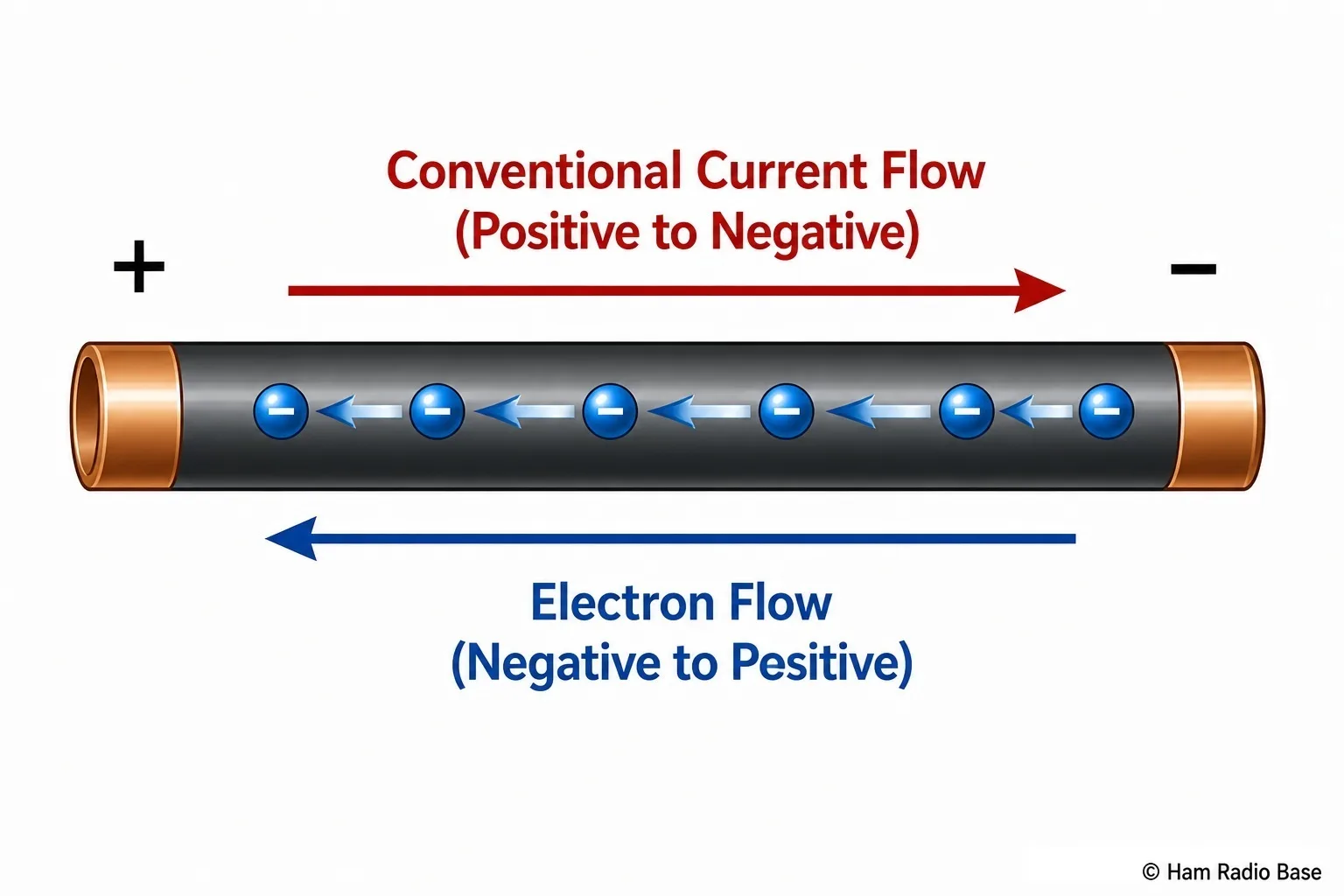
There are two ways to describe the direction of current in a circuit, and it is important to understand both. Conventional current flows from the positive terminal of the source, through the external circuit, to the negative terminal. This convention was established before the electron was discovered, and it is the one used in all circuit diagrams, Ohm's Law, Kirchhoff's Laws and every formula you will encounter in this course.
Electron flow is the physical reality: electrons carry negative charge and are attracted toward the positive terminal, so they actually move from negative to positive — the opposite direction to conventional current. For all power and voltage calculations the two conventions give identical results, so there is nothing to change. When you see an arrow on a circuit diagram, it shows conventional current direction.
DC and AC Current
DC (direct current) flows in one direction continuously. The level may be constant — steady DC, as from a well-regulated bench supply — or it may vary in magnitude (pulsating DC), but it never reverses polarity. Batteries and regulated power supplies all provide DC. The current drawn from a 13.8 V ham radio power supply flows in one direction around the circuit at all times.
AC (alternating current) periodically reverses direction. Utility power alternates at 50 Hz in Europe and Australia (50 complete cycles per second) or 60 Hz in North America. In an RF circuit the current reverses millions of times per second — when you transmit on 14 MHz, the current in the antenna element reverses direction 14,000,000 times every second. Understanding AC behavior is fundamental to understanding coaxial cables, antennas, filters and impedance matching, all of which are covered in later modules.
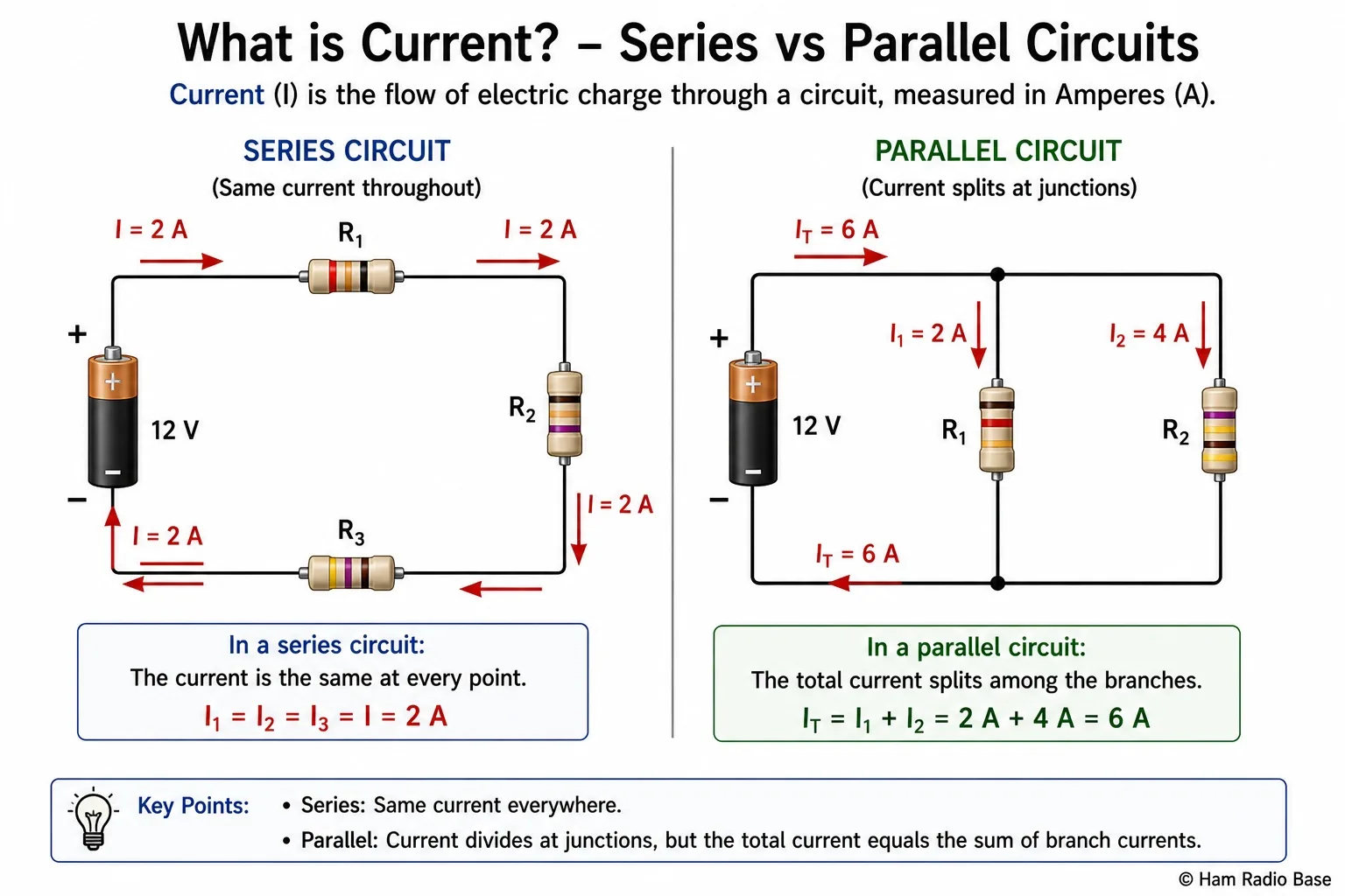
Current in Series and Parallel Circuits
This rule pair is used constantly in electronics work. In a series circuit — where components are connected end to end in a single loop — the same current flows through every component. If 500 mA enters the first resistor, then 500 mA also flows through the second resistor, the third, and every other element in the chain. There is nowhere else for the charge to go.
In a parallel circuit — where components share the same two nodes — the current from the supply splits between the branches. The branch with lower resistance carries more current. The total current drawn from the supply equals the sum of all individual branch currents. A complete treatment of series and parallel circuit analysis, including worked calculations, is in Module 5.
Ham Radio Applications of Current
Understanding current directly shapes how you wire, fuse and power your station equipment.
- Transceiver power consumption: Power equals voltage multiplied by current — P = V × I. A 100 W transceiver running from a 13.8 V supply draws approximately 15 A on transmit (100 / 13.8 ≈ 7.2 A of RF output, but the PA is not 100% efficient, so total DC draw is higher). Use the correct fuse rating and adequate cable gauge for that current.
- Current sensing for protection: Many linear amplifiers sample the DC supply current using a small-value shunt resistor. The voltage drop across that resistor is proportional to current. If the current exceeds a safe threshold — indicating an overload or fault condition — protection circuitry can key down or cut off the drive signal.
- Receive vs transmit current: Most HF transceivers draw only about 2 A on receive, powering digital processing, the display and audio circuitry. The moment you press transmit, current jumps to 15–22 A as the power amplifier stage takes over. Always size your power supply and cabling for the transmit current, not receive.
Frequently Asked Questions
What is a milliampere?
1 milliampere (mA) = 1/1000 of an ampere = 0.001 A. Many electronic circuits operate at currents measured in milliamps or even microamperes (µA, 1/1,000,000 A). LED indicators typically draw 10–20 mA. A handheld radio in receive mode draws around 50–150 mA. RF signal levels inside a receiver front end are often in the nanoampere (nA) or microampere range. It is worth memorising these conversions: 1000 µA = 1 mA, 1000 mA = 1 A.
Why must an ammeter be connected in series, not in parallel?
An ammeter is designed to measure the current flowing through it — so all the current in that branch must pass through the meter. An ammeter has very low internal resistance (near zero), which means connecting it in parallel would essentially short-circuit the component next to it, potentially blowing the meter fuse or damaging the circuit. A voltmeter, by contrast, has very high internal resistance and is connected in parallel across the component.
What is the difference between current and charge?
Charge (Q) is measured in coulombs (C) and represents a quantity of electrons. Current (I) is measured in amperes and represents the rate of charge flow: I = Q/t, where t is time in seconds. Charge is the "stuff" and current is how fast that stuff moves. An analogy: charge is the volume of water in a pipe and current is the flow rate in liters per second.
Can current flow through a vacuum?
Yes — in a vacuum tube (valve), electrons are emitted from a hot cathode and travel across a vacuum to reach an anode. This is thermionic emission. Vacuum tubes were the basis of all radio electronics before transistors were developed, and they are still used in some high-power RF amplifiers today because of their ability to handle very high voltages and power levels.
Test Your Knowledge
Answer the questions below to check your understanding. Every answer can be found in the lesson above.