What Is Resistance
Resistance is the third of the three fundamental electrical quantities, alongside voltage and current. It describes how strongly a material or component opposes the flow of electric current. High resistance means little current flows for a given voltage; low resistance means a lot of current flows. Every conductor has some resistance, and resistors are components designed to have a specific, controlled value of resistance.
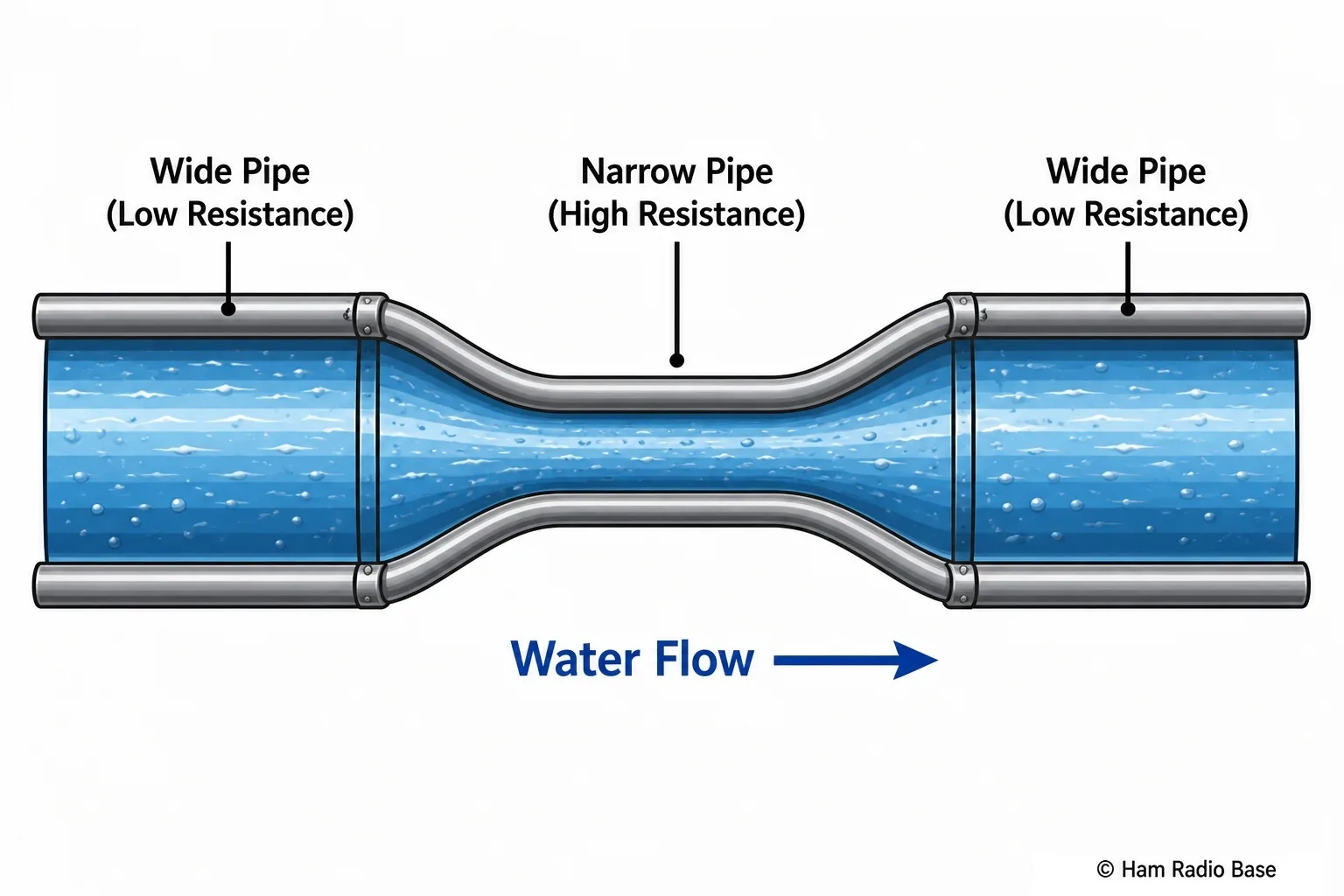
What Causes Resistance
Think of water flowing through a pipe. A wide pipe offers little resistance to the flow; a narrow pipe restricts it. Electricity behaves in a similar way. When free electrons drift through a conductor, they do not travel in a straight unobstructed path — they collide with the fixed positive ions that make up the crystal lattice of the material. Each collision slows the electron down and transfers energy from the electrical current to the lattice. That transferred energy appears as heat.
This is resistance: the cumulative effect of all those collisions impeding the drift of charge. It is why resistors warm up when current passes through them, and why long thin cables lose power — resistance is continuously converting electrical energy into thermal energy. The thicker or shorter the conductor, and the fewer collisions per unit length, the lower the resistance.
The Ohm
Resistance is measured in ohms, symbol Ω (the Greek letter omega). The definition follows directly from Ohm's Law: 1 Ω = 1 V/A. A resistance of one ohm allows a current of one ampere to flow when one volt is applied across it.
Practical resistance values span an enormous range, so two prefixes are used constantly:
- Kilohm (kΩ) = 1,000 Ω
- Megohm (MΩ) = 1,000,000 Ω
To put real-world values in context: a short piece of copper connecting wire measures in the milliohm range; a carbon-film resistor used to limit LED current is typically hundreds of ohms; a pull-up resistor on a logic line is commonly 4.7 kΩ to 10 kΩ; the input impedance of a multimeter set to measure voltage is typically 10 MΩ — high enough that connecting it does not disturb the circuit significantly.
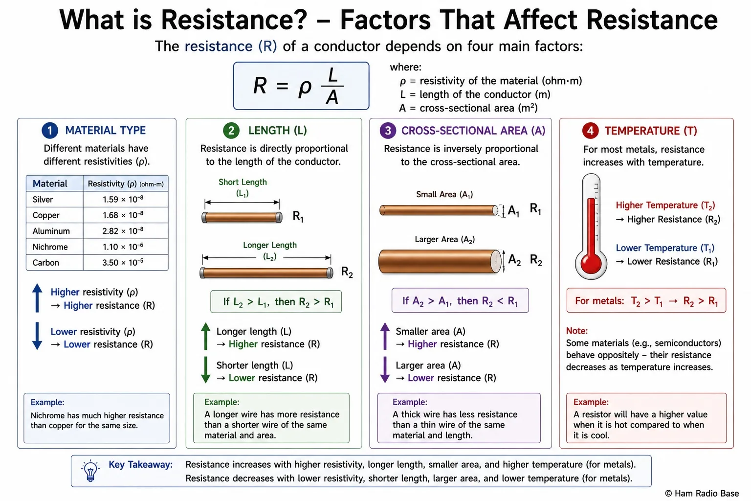
Factors That Affect Resistance
The resistance of a conductor depends on four physical properties:
- Material (resistivity): Different materials have different resistivities (ρ), measured in Ω·m. Copper has very low resistivity (1.68 × 10⁻⁸ Ω·m), making it ideal for wiring. Nichrome wire has much higher resistivity, which is why it is used in heating elements and current-limiting wirewound resistors.
- Length: Resistance is proportional to length (R ∝ length). Doubling the length of a wire doubles its resistance. This is why long DC power leads in a vehicle cause noticeable voltage drop at the transceiver end.
- Cross-sectional area: Resistance is inversely proportional to cross-sectional area (R ∝ 1/area). A thicker wire has more parallel paths for electrons, lowering resistance. Doubling the wire's cross-sectional area halves its resistance. This is why high-current conductors — such as cables running to a linear amplifier — must be heavy-gauge wire.
- Temperature: For most metals, resistance increases with temperature. This is described by the temperature coefficient (α). For copper, α ≈ +0.004 per °C — about a 0.4% increase per degree Celsius rise. A power resistor that heats up significantly when carrying current will have a slightly different resistance value than when cold. This is worth keeping in mind when designing precision circuits.
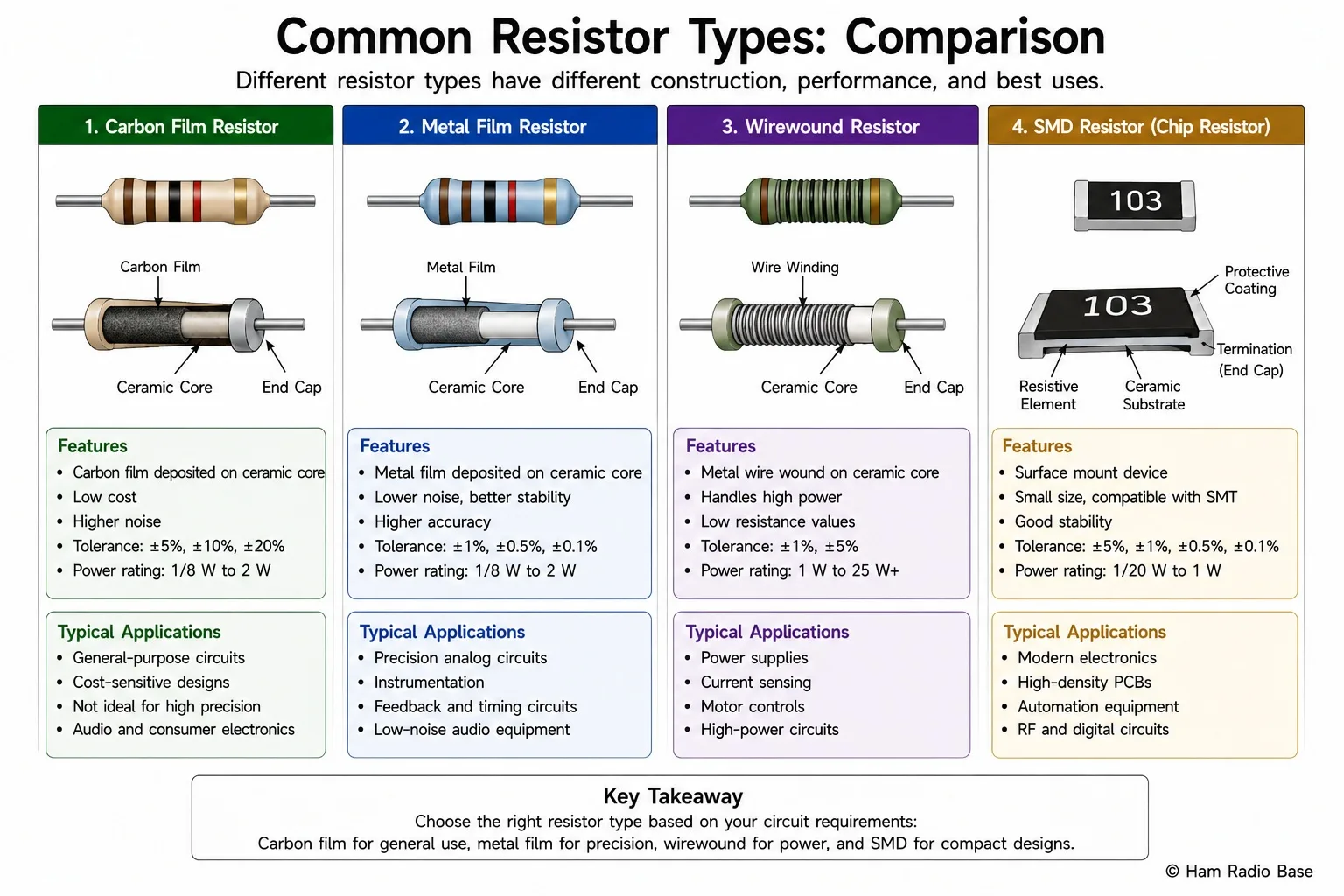
Resistors as Components
A resistor is a passive component manufactured to have a specific, stable value of resistance. They are the most common component in electronic circuits. Several construction types exist, each suited to different applications:
- Carbon film: A thin film of carbon deposited on a ceramic rod. Common, low cost, general purpose. Tolerance typically ±5%.
- Metal film: A thin film of metal alloy. Better stability, tighter tolerance (±1%), lower noise. Preferred for precision and audio circuits.
- Wirewound: Resistance wire wound on a ceramic former. Used where high power dissipation is needed — dummy loads, current-sense shunts. Can be inductive, which matters at RF frequencies.
- SMD chip resistors: Surface-mount rectangular chips. Used on modern PCBs. Values marked in a 3- or 4-digit code.
Two specifications apply to every resistor:
- Power rating: The maximum continuous power the component can dissipate without overheating. Common ratings are 0.125 W, 0.25 W, 0.5 W, 1 W and 5 W. Exceeding the power rating causes the resistor to overheat and can change its value permanently or destroy it.
- Tolerance: How close the actual resistance is to the stated value — expressed as a percentage (±1%, ±5%, ±10%). Through-hole resistors carry their value in a color-coded band system, which is covered in detail in Module 3.
Resistors in Series and Parallel
A full treatment is in Module 5, but the two key rules are introduced here because you will encounter them immediately:
- Series: Rtotal = R1 + R2 + R3 + … — resistances add directly. Each resistor in the chain contributes to the total. Two 100 Ω resistors in series give 200 Ω.
- Parallel: 1/Rtotal = 1/R1 + 1/R2 + … — the total resistance is always less than the smallest individual branch. Two equal resistors in parallel give exactly half the resistance of one. Two 50 Ω dummy loads connected in parallel present a combined load of 25 Ω.
Understanding which topology applies in a given circuit is the foundation of all circuit analysis that follows.
Ham Radio Applications
Resistance and resistors appear in almost every part of a radio station, from the antenna feed through to the front panel indicators.
- Current-limiting for LED indicators: An LED on the front panel draws 20 mA at 2 V forward voltage. The supply is 13.8 V. The series resistor must drop the remaining 11.8 V (13.8 − 2 = 11.8 V) at 20 mA. Using Ohm's Law: R = V/I = 11.8 / 0.02 = 590 Ω. The nearest standard values are 560 Ω and 620 Ω — either is suitable.
- Voltage dividers: Two resistors connected in series from the supply rail to ground create a stable intermediate voltage at their junction. This technique is used to generate bias voltages for transistor stages and to scale a higher voltage down to the range of an ADC or monitoring circuit.
- Dummy loads: A non-inductive resistor (or bank of resistors) presenting exactly 50 Ω to the transmitter absorbs all output power without radiating. Essential for testing, alignment and amplifier tuning. Because P = V²/R = I²R, a 100 W dummy load must dissipate 100 W continuously — wirewound resistors rated for this, often oil-cooled, are used.
- Cable resistance and voltage drop: AWG 12 copper wire has a resistance of approximately 5.2 mΩ per metre. A 10 A current through a 5 m cable run (10 m total for the round trip) produces a voltage drop of V = I × R = 10 × 0.052 = 0.52 V. In a 13.8 V system, that is a 3.8% loss. Using adequately sized wire keeps voltage drop to an acceptable level and prevents the cable from heating.
Frequently Asked Questions
Is there any conductor with zero resistance?
Ordinary conductors at normal temperatures always have some resistance. However, certain materials become superconductors when cooled to very low temperatures (close to absolute zero, −273°C). Below a critical temperature, their resistance drops to exactly zero — current can flow indefinitely with no energy loss. Superconductors are used in MRI machines, particle accelerators and some experimental power transmission systems. For everyday electronics and amateur radio, all conductors have non-zero resistance.
What is the difference between resistance and impedance?
Resistance is the opposition to current in a purely resistive circuit — it is the same regardless of frequency. Impedance is the more general term used in AC circuits. Impedance (Z) includes resistance (R) plus reactance (X), where reactance is the opposition caused by capacitors and inductors. Reactance depends on frequency. At DC (0 Hz), capacitors block current entirely (infinite reactance) and inductors are just their DC winding resistance. At radio frequencies, both components have significant reactance. Impedance is covered in Module 6.
Why do wires have resistance if copper is a good conductor?
All materials have some resistivity — even the best conductors. Copper has very low resistivity, so a short thick wire has a very small resistance — often less than a milliohm. But run enough current through enough length of wire and the resistance adds up. At 10 A through 1 Ω of wire resistance, you waste 100 W as heat (P = I²R = 100 × 1 = 100 W) and drop 10 V across the cable. Cable selection for power wiring is primarily about managing this resistance to keep losses and voltage drops acceptable.
What does it mean when a resistor is "out of tolerance"?
Every resistor is manufactured with a stated tolerance, such as ±5%. A 100 Ω ±5% resistor will have an actual value between 95 Ω and 105 Ω. If a resistor measures outside that range, it is out of tolerance. This happens due to ageing, overheating or manufacturing variability. For most audio and RF circuits, a ±5% resistor is perfectly adequate. Precision circuits — such as voltage references and measurement equipment — need ±1% or better metal-film resistors.
Test Your Knowledge
Answer the questions below to check your understanding. Every answer can be found in the lesson above.