Balanced Modulators and Mixers
Every SSB transmitter, every superhet receiver, every frequency converter, and every phase detector contains a mixer — a circuit that multiplies two signals and produces their sum and difference frequencies. The balanced modulator is a specialized mixer that cancels one of the two input signals in the output, leaving only the product terms. Understanding how mixers and balanced modulators work, what they produce, and what limits their performance (conversion loss, intermodulation, third-order intercept) is essential for understanding the transmitters and receivers you use every day. This lesson builds from the ideal multiplier through the diode ring mixer to the IC Gilbert cell, then applies these concepts to the SSB transmitter chain.
The Ideal Multiplier
The foundation of all mixing is the trigonometric product formula. When two sinusoidal signals are multiplied together:
cos(2πf1t) × cos(2πf2t) = ½cos(2π(f1−f2)t) + ½cos(2π(f1+f2)t)
The output contains only sum and difference frequencies — the original frequencies f1 and f2 do not appear.
An ideal mixer produces exactly this output: the sum frequency (f1 + f2) and the difference frequency (|f1 − f2|). In a receiver, the mixer converts an incoming RF signal to the IF by mixing it with the local oscillator (LO). In a transmitter, it shifts a baseband or low-frequency signal up to the RF output frequency. Filters select the desired output (usually the difference, called the "IF product" in a receiver) and reject the unwanted sum or image.
RF input: 14.200 MHz (20m SSB station)
LO: 14.655 MHz (high-side injection)
Difference: 14.655 − 14.200 = 0.455 MHz = 455 kHz (IF)
Sum: 14.655 + 14.200 = 28.855 MHz (rejected by IF filter)
The IF filter at 455 kHz passes only the desired down-converted signal.
The Balanced Modulator
A balanced modulator is a mixer specifically designed to cancel (suppress) one of its input signals from the output. In SSB transmitter circuits, the balanced modulator multiplies the audio signal by the carrier, producing double-sideband suppressed-carrier (DSB-SC) output — both sidebands are present, but the carrier is absent from the output.
The cancellation is achieved through circuit symmetry. In a single-diode or single-transistor AM modulator, the output contains the carrier (fundamental), sidebands (carrier ± audio), and harmonics. A balanced modulator uses a second path, driven 180° out of phase, to cancel the carrier and even-order products while the odd-order products (including the desired sidebands) add constructively.
Input: carrier fc, audio fa
Output: fc + fa (USB) and fc − fa (LSB)
Suppressed: fc (carrier) — typically 40–60 dB below the sidebands
This is DSB-SC: double-sideband, suppressed-carrier.
The Diode Ring (Double-Balanced Mixer)
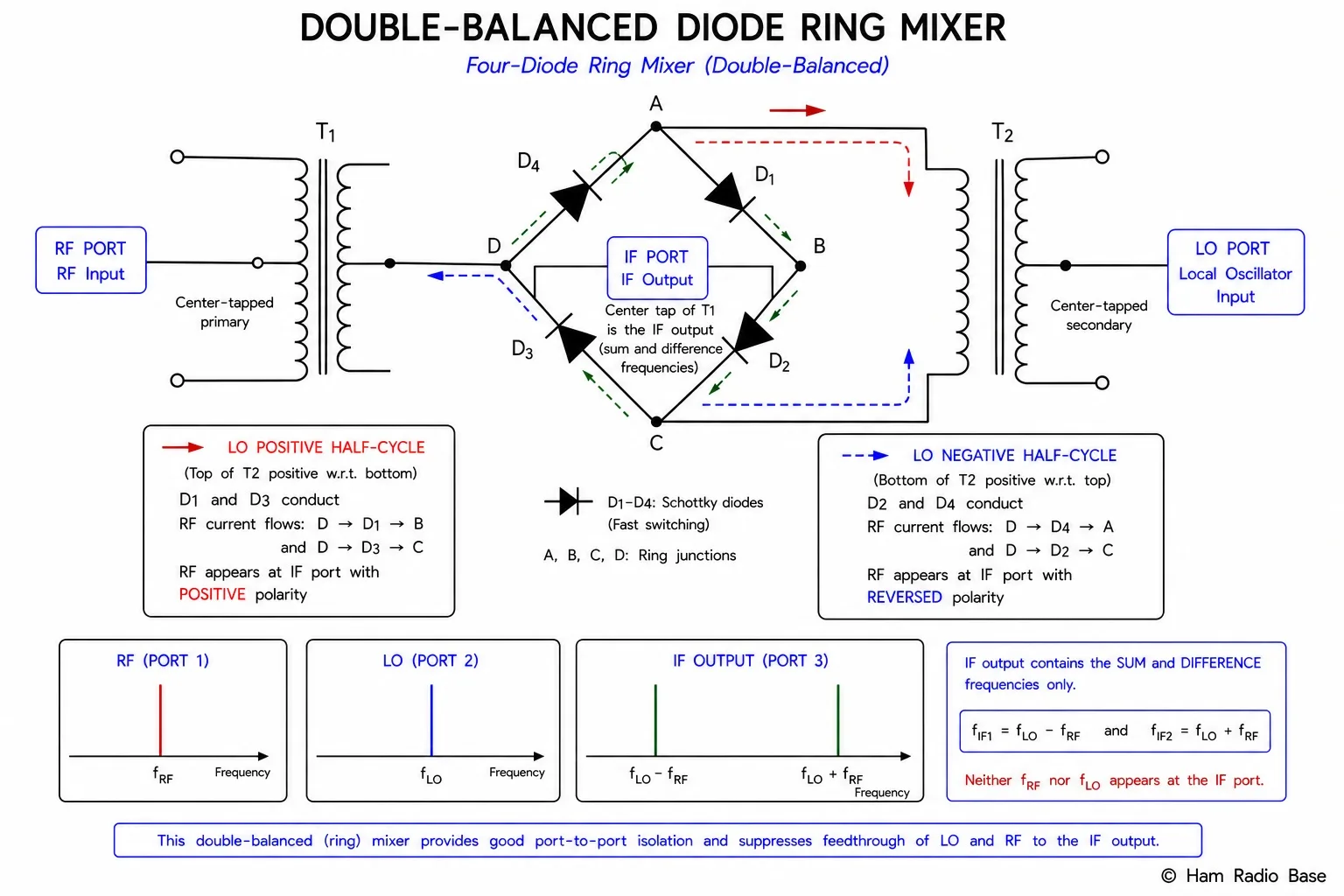
The most widely used passive mixer topology is the four-diode ring, also called the double-balanced mixer (DBM) or lattice mixer. Four matched diodes are arranged in a bridge (ring) configuration between three transformers: RF input, LO input, and IF output.
Operation in two half-cycles:
- LO positive half-cycle: Diodes D1 and D3 conduct; D2 and D4 are reverse-biased. The RF signal appears at the IF port with positive polarity (multiplication by +1).
- LO negative half-cycle: Diodes D2 and D4 conduct; D1 and D3 are off. The RF signal appears at the IF port with reversed polarity (multiplication by −1).
The ring alternates between +1 and −1 at the LO rate — this is equivalent to multiplying the RF signal by a square wave at the LO frequency. A square wave contains the fundamental (fLO) and odd harmonics (3fLO, 5fLO, ...); therefore the output contains mixing products at (nfLO ± fRF) for all odd n. By symmetry:
- The RF feed-through to the IF port is cancelled (balanced input transformer).
- The LO feed-through to the IF port is cancelled (balanced output transformer).
- The LO feed-through to the RF port is cancelled (balanced LO transformer).
- LO-to-IF isolation: 40–60 dB
- LO-to-RF isolation: 40–60 dB
- RF-to-IF conversion loss: 6–8 dB (passive ring)
- Carrier suppression (as balanced modulator): 40–60 dB
The Gilbert Cell
The Gilbert cell is an active differential mixer built from transistors (BJT or FET pairs). It consists of a lower differential pair that amplifies the RF input, with the current steered between two upper differential pairs by the LO signal. The output currents from the upper pairs are cross-coupled, causing the LO signal to commutate the RF signal (multiply by ±1) with low noise.
Compared to the diode ring mixer:
- Conversion gain instead of conversion loss (typically +10 to +20 dB).
- Compatible with low LO drive levels (the transistor differential pair switches at millivolts, not the +7 to +17 dBm needed by a diode ring).
- Excellent port isolation from the differential structure.
- Lower IP3 than a good diode ring for high dynamic range applications.
Gilbert cell ICs include the NE612/NE602 (popular in homebrew receiver kits), SA612, MC1496, and many monolithic RF IC devices. The SA612/NE612 integrates Gilbert cell, internal oscillator, and voltage regulator in a single 8-pin DIP package, making it a complete receiver front end or balanced modulator at minimal cost.
Mixer Specifications
Conversion Loss
Passive mixers (diode ring) do not amplify — they attenuate the desired output signal. Conversion loss (CL) is the ratio of output power (at the IF frequency) to input power (at the RF frequency):
Typical diode ring: CL = 6–8 dB
LO Drive Level
Diode ring mixers require a minimum LO power to fully switch the diodes on each half-cycle. Common LO drive ratings: +7 dBm (low-level), +13 dBm (standard), +17 dBm (high-level), +23 dBm (very high-level). Higher LO drive provides better linearity (higher IP3) at the cost of LO isolation and increased power.
Third-Order Intercept Point (IP3)
IP3 is the most important mixer linearity specification. It describes the input signal level at which the third-order intermodulation products (2f1−f2 and 2f2−f1) would theoretically equal the desired output — the intersection point of two extrapolated lines on a plot of output power vs input power. Higher IP3 means better handling of strong signals without generating false signals.
Typical values:
- NE612 Gilbert cell: IIP3 ≈ −10 to −15 dBm (low — limited to weak-signal applications)
- DBM (+7 dBm LO): IIP3 ≈ +12 to +15 dBm
- DBM (+17 dBm LO): IIP3 ≈ +25 to +30 dBm
- High-level DBM (+23 dBm LO): IIP3 ≈ +35 to +40 dBm
Intermodulation Products
When two or more strong signals at frequencies f1 and f2 enter a nonlinear device (mixer, amplifier, detector), intermodulation products are generated at frequencies that are linear combinations of the input frequencies:
mf1 ± nf2 for integers m, n (order = |m| + |n|)
Third-order products (most problematic):
2f1 − f2 and 2f2 − f1
These fall close to the original signals and cannot be easily filtered out.
Two strong signals enter a receiver front end: f1 = 14.200 MHz, f2 = 14.210 MHz
Third-order products:
2f1 − f2 = 2(14.200) − 14.210 = 28.400 − 14.210 = 14.190 MHz
2f2 − f1 = 2(14.210) − 14.200 = 28.420 − 14.200 = 14.220 MHz
Both products fall within the 20m SSB band, 10 kHz away from the original signals — right where other stations are operating. If the receiver front end has insufficient IP3, these phantom signals will appear on the received audio.
Balanced Modulators in the SSB Transmitter
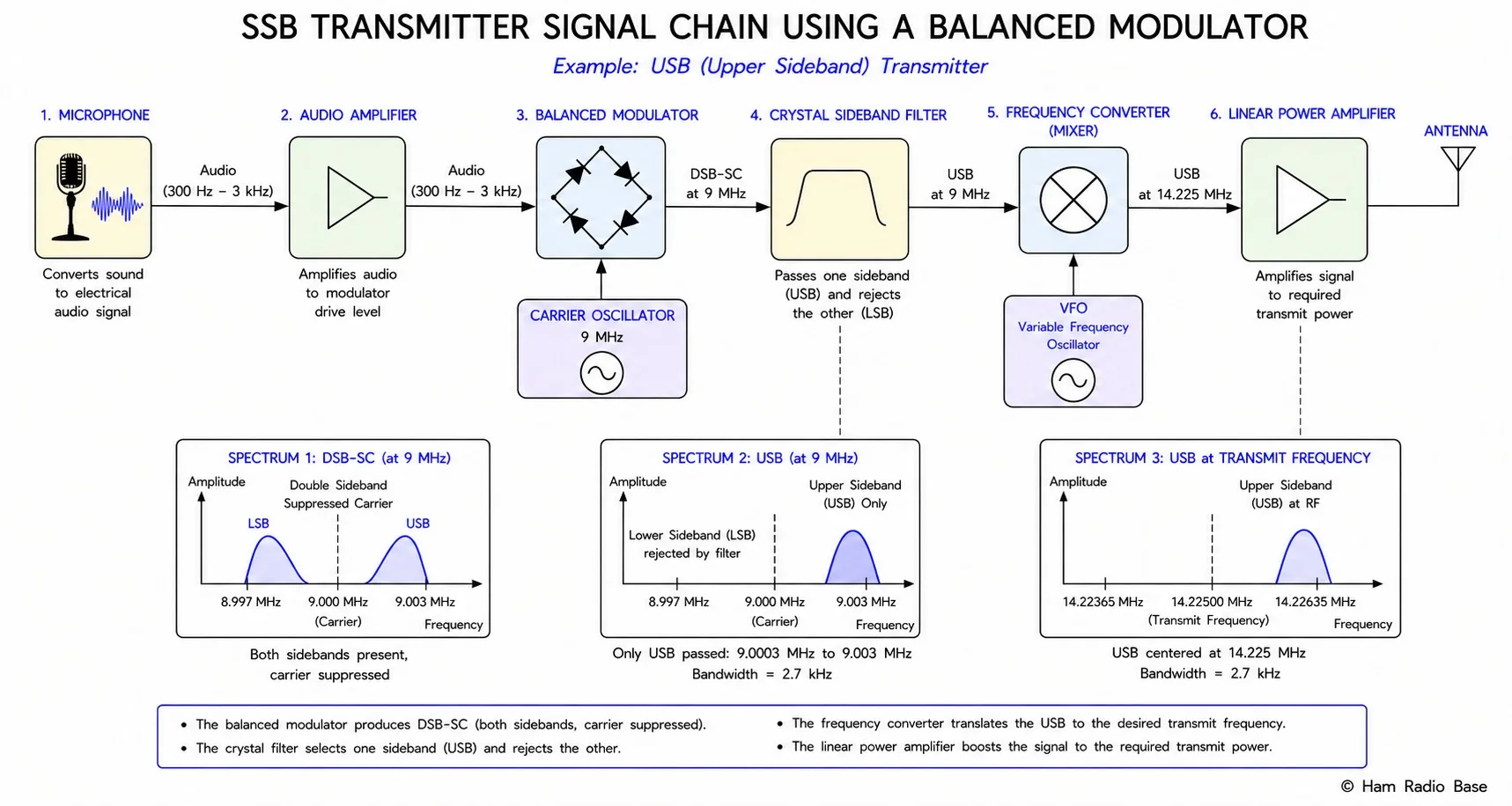
The filter-method SSB transmitter uses a balanced modulator to generate DSB-SC, then uses a sharp crystal filter to select one sideband:
- Microphone → Audio amplifier: Voice signal, 300–3,000 Hz.
- Balanced modulator: Audio multiplied by a fixed carrier (typically 8–9 MHz or 455 kHz). Output is DSB-SC — both sidebands, no carrier.
- Sideband filter: A crystal ladder filter or monolithic crystal filter with 2.4–2.7 kHz passband and 50+ dB rejection at the opposite sideband frequency. Selects USB or LSB depending on which side of the carrier the filter is centered.
- Up-converter (mixer): Mixes the IF SSB signal with the VFO to reach the final operating frequency. May involve multiple conversion stages.
- Driver and PA: Linear amplification — must be linear to avoid distorting the SSB envelope.
Frequently Asked Questions
Why does the diode ring mixer suppress both the RF and LO signals at the IF port?
The ring mixer's transformers are wound so that when the LO positive half-cycle switches D1/D3 on, the RF signal appears at the IF output with one polarity; when the LO negative half-cycle switches D2/D4 on, it appears with the opposite polarity. The LO fundamental frequency drives the ring with equal but opposite voltages that cancel at the IF output transformer — the LO itself does not appear at IF. Similarly, the RF transformer center-tap arrangement prevents the RF frequency from passing directly to the IF port. Only the mixing products (sum and difference of RF and LO) appear at IF because their phases add constructively. This double-balance — RF suppressed and LO suppressed — is why it is called a double-balanced mixer.
What is carrier suppression and why does it matter for SSB?
Carrier suppression is the ratio of the carrier component power to the sideband power at the balanced modulator output, expressed in dB. A perfect balanced modulator would have infinite carrier suppression — in practice, small mismatches between the diode pairs (slightly different forward voltages, junction capacitances) cause imperfect cancellation. Typical carrier suppression: 40–60 dB. In the SSB transmitter chain, the sideband filter provides an additional 50+ dB of carrier attenuation, so the cascade suppression is 90–110 dB — the carrier is completely undetectable in the final output. Inadequate carrier suppression causes the transmitted signal to sound like AM instead of SSB, wastes power on an uninformative carrier, and widens the occupied bandwidth unnecessarily.
What is conversion loss and why do passive mixers have it?
Conversion loss is the difference in power between the RF input signal and the desired IF output signal, expressed in dB. Passive mixers (diode rings) have conversion loss because the mixing process spreads the input signal power among many output frequencies — the desired difference (or sum) product, plus the image product, plus all the odd-harmonic mixing products. Only a fraction of the input power ends up in the desired IF band; the rest appears at other frequencies and is lost (or must be filtered out). For an ideal diode ring, the theoretical minimum conversion loss is about 3.9 dB (due to the harmonic content of the square-wave LO switching); real mixers add 2–4 dB of resistive losses, giving 6–8 dB total conversion loss. Active mixers (Gilbert cell) add gain from the transistor amplification, producing conversion gain instead of loss.
How do third-order intermodulation products affect a receiver?
Third-order intermodulation (IM3) occurs when two strong signals (f1, f2) at the receiver front end generate phantom signals at 2f1−f2 and 2f2−f1. These phantom signals appear on the receiver's display and in the audio output as if they were real transmissions — the operator cannot distinguish them from real signals by tuning behavior alone. The phantom signals are internally generated distortion products, not actual transmissions from other stations. On a crowded band (e.g., 40m during a contest with dozens of strong stations), a receiver with poor IP3 can show dozens of phantom signals mixed among real ones, making the band appear busier than it is and causing interference to weak legitimate signals. High-IP3 front ends (achieved through good mixer design, low-noise amplifier choice, and input filtering) are essential for operating on busy bands.
Why must an SSB PA be linear but an FM PA can be nonlinear?
An SSB signal carries information in both the amplitude and phase of the RF envelope — voice content modulates both the instantaneous amplitude and the frequency/phase of the carrier. Any compression or clipping of the amplitude by a nonlinear PA distorts this information: the recovered audio is distorted and intermodulation products splatter into adjacent channels. An FM signal carries information only in the instantaneous frequency; the amplitude is constant. A nonlinear (even a hard-clipping) PA that clips the FM envelope does not destroy the frequency information — the frequency deviations are preserved through clipping. Therefore FM transmitters can use efficient Class C PAs (which are inherently nonlinear), while SSB transmitters must use linear Class A or Class AB PAs, accepting the efficiency penalty in exchange for signal integrity.
Test Your Knowledge
Answer the questions below to check your understanding of balanced modulators and mixers.