Detectors and Demodulators
A demodulator (or detector) is the circuit that extracts the original information — voice, data, Morse code — from a modulated RF or IF signal. Every receiver must have one, and the demodulator circuit is matched to the modulation scheme in use: an AM receiver uses an envelope detector, an SSB or CW receiver uses a product detector, and an FM receiver uses a discriminator or phase-locked loop. Use the wrong detector and you recover nothing useful; use the right one and you recover the original signal with high fidelity. This lesson examines each detector type in detail — the circuit, the physics of operation, the limitations, and the practical considerations for amateur radio use.
The AM Envelope Detector
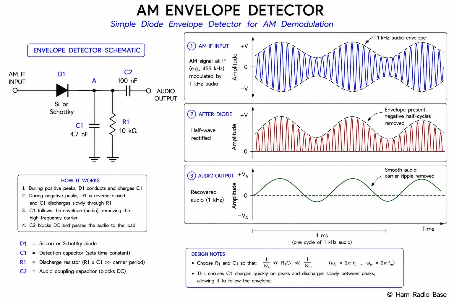
The simplest AM detector is the envelope detector — a half-wave rectifier followed by an RC low-pass filter. The diode passes only positive half-cycles of the IF signal, charging the capacitor to the peak voltage. Between peaks, the capacitor discharges through the resistor. If RC is chosen correctly, the capacitor voltage follows the slowly varying envelope of the AM signal — which is exactly the audio waveform.
1/fIF << RC << 1/faudio,max
Example: IF = 455 kHz (period = 2.2 μs), audio max = 3 kHz (period = 333 μs)
RC should be between 2.2 μs and 333 μs — typically 10–100 μs
Common values: R = 10 kΩ, C = 0.01 μF → RC = 100 μs ✓
If RC is too long (too slow), the capacitor cannot discharge fast enough to follow fast audio transients — the output clips on negative audio peaks. This is called diagonal clipping and produces severe audio distortion. If RC is too short (too fast), the output follows individual RF cycles rather than the envelope — no detection occurs.
Maximum rate of change of envelope must not exceed RC discharge rate.
For a sinusoidal tone at frequency fa and modulation depth m:
Clipping occurs if RC > 1/(2πfa · m)
At m = 1 (100% mod), fa = 3 kHz: RC must be less than 1/(2π×3000) = 53 μs
The diode in an envelope detector must have a low forward voltage drop compared to the minimum signal level to detect. Silicon diodes (Vf ≈ 0.6 V) work for strong signals; germanium or Schottky diodes (Vf ≈ 0.2–0.3 V) are preferred for weak signals. In a superhet receiver, the IF amplifier brings the signal level up to several hundred millivolts, making silicon diodes entirely adequate.
The Product Detector (SSB and CW)
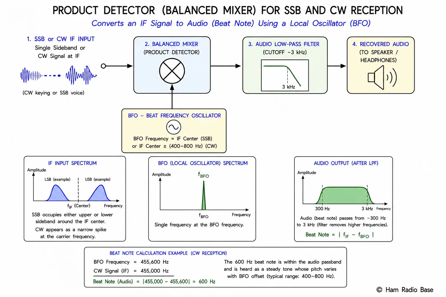
SSB and CW signals cannot be detected by an envelope detector — SSB has a varying envelope that doesn't correspond to the audio, and CW at constant amplitude has no envelope variation at all. Both require a product detector: a circuit that multiplies the incoming IF signal by a locally generated reference signal (the beat-frequency oscillator, or BFO) to produce a difference-frequency output in the audio band.
Input: VIF(t) = Vs · cos(2πfIFt + φ(t))
BFO: VBFO(t) = VBFO · cos(2πfBFOt)
Product: VIF × VBFO = ½VsVBFO[cos(2π(fIF−fBFO)t + φ) + cos(2π(fIF+fBFO)t + φ)]
Low-pass filter removes the sum term, leaving:
Vaudio(t) = ½VsVBFO · cos(2π(fIF−fBFO)t + φ)
For SSB reception: the BFO is set to the suppressed carrier frequency (offset from IF center by the audio suppression frequency, typically just at the edge of the IF filter passband). The difference frequency (fIF − fBFO) maps each USB or LSB frequency component to the correct audio frequency. The φ(t) term carries the original audio modulation — it is exactly the baseband audio signal.
For CW reception: the BFO is offset from the IF by 400–800 Hz, producing a constant beat note pitch. When the key is down, the beat note is present. When the key is up, there is no signal and no beat note.
Product detectors can be built from balanced modulators (diode rings or Gilbert cells operating in detector mode), or from dedicated ICs such as the NE612 or SA612. The output is inherently low in amplitude and requires audio amplification.
The Foster-Seeley FM Discriminator
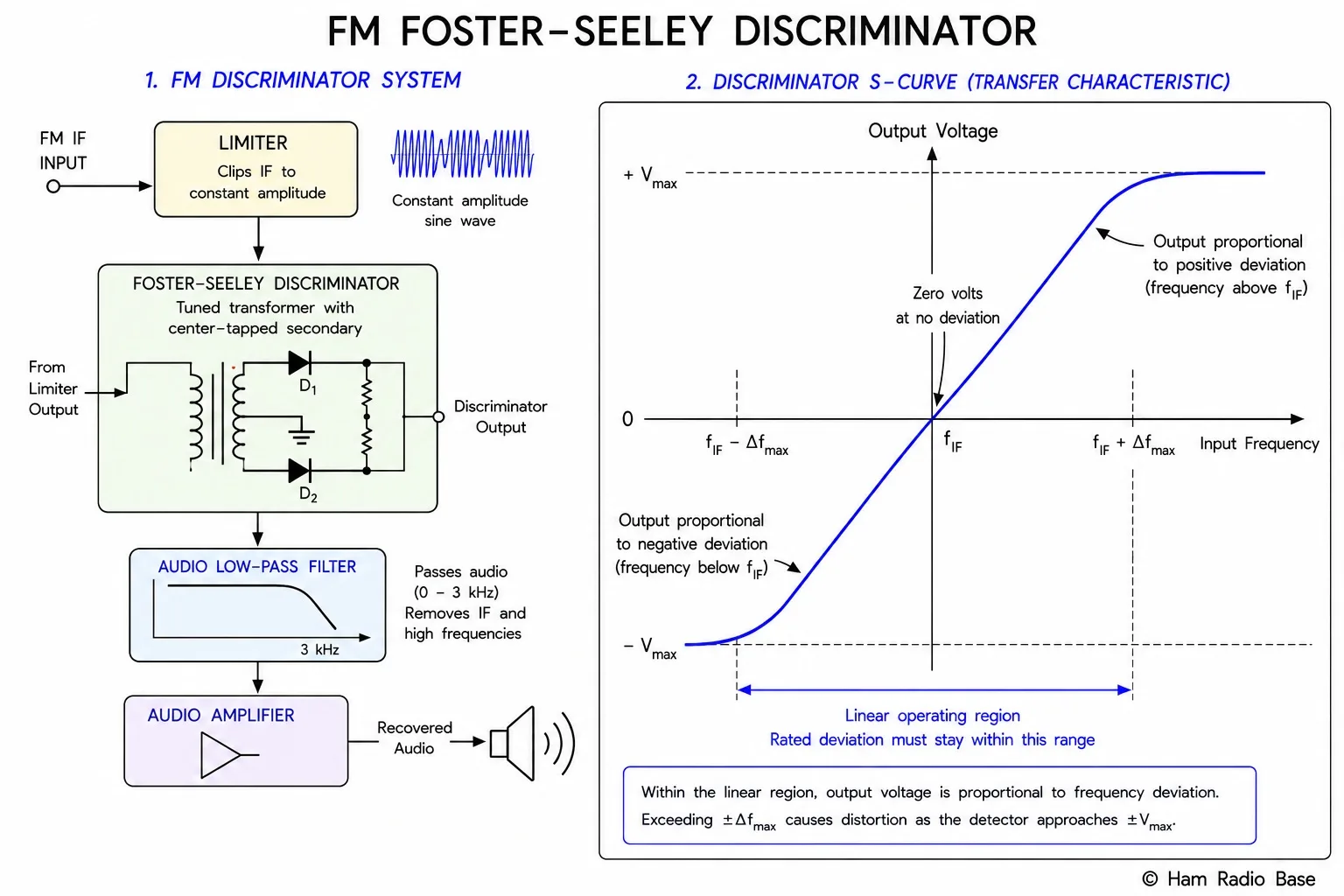
The Foster-Seeley discriminator converts FM frequency variations directly to audio voltage. It uses a carefully balanced transformer circuit where the relative phase between the primary and secondary windings changes with input frequency. Two diode-RC detector stages, driven in opposite polarity, produce an output proportional to the phase (and therefore frequency) deviation from the IF center frequency.
The discriminator's key characteristic is its S-curve response: output voltage vs. input frequency traces an S-shaped curve that passes through zero at the IF center frequency and is approximately linear over the useful deviation range. The slope of the linear region — called the discriminator sensitivity — is measured in millivolts per kilohertz (mV/kHz).
- Output voltage proportional to frequency deviation from IF center
- Linear S-curve response over ±1.5× peak deviation range typically
- Responds to AM as well as FM — requires a limiter stage before the discriminator
- Discriminator sensitivity: typically 0.5–2 V per kHz of deviation
- Requires well-aligned center frequency (correct IF) for zero-output at unmodulated carrier
The critical limitation of the Foster-Seeley discriminator is its sensitivity to amplitude variations — it responds to AM as well as FM. An FM receiver using a Foster-Seeley discriminator must include a limiter (a hard-clipping amplifier that removes amplitude variations) immediately before the discriminator. Without the limiter, noise bursts and fading cause amplitude variations that appear as audio distortion at the output.
The Ratio Detector
The ratio detector was developed specifically to address the Foster-Seeley's sensitivity to AM. It is structurally similar to the Foster-Seeley but uses two diodes connected differently and adds a large electrolytic capacitor (typically 5–50 μF) across the output. This capacitor stores the total carrier energy over many RF cycles; the output voltage is derived as the ratio of individual diode output voltages to the stored total — hence "ratio detector."
| Property | Foster-Seeley | Ratio Detector |
|---|---|---|
| AM rejection | None (needs limiter) | Inherent (no limiter needed) |
| Audio output level | Higher | Lower (ratio division) |
| Circuit complexity | Moderate | Slightly more complex |
| Cost advantage | None | Eliminates limiter stage |
| Used in | High-quality FM tuners | Consumer FM tuners, car radios |
The ratio detector's AM rejection works because the large storage capacitor holds the sum of both diode outputs constant; changes in carrier amplitude change both diodes equally, leaving their ratio unchanged. Only frequency-induced changes in relative phase shift the ratio between the two diodes, producing audio output. The AM rejection of a well-designed ratio detector is 30–40 dB, sufficient for most practical applications without a separate limiter.
PLL FM Demodulator
A phase-locked loop (PLL) can demodulate FM by exploiting the same property it uses for carrier synthesis: the VCO error voltage tracks the incoming frequency. In FM demodulation mode:
- The incoming FM signal is connected to the PLL's phase comparator input.
- The VCO is adjusted to a free-running frequency equal to the unmodulated IF center frequency.
- The PLL phase comparator generates an error voltage proportional to the phase difference between the incoming FM signal and the VCO output.
- This error voltage, after filtering, drives the VCO to track the instantaneous frequency of the FM signal.
- The error voltage at the output of the loop filter is proportional to the frequency deviation from the center — it is the demodulated audio.
- Excellent linearity (VCO error voltage is directly proportional to frequency deviation)
- Inherent AM rejection (phase comparator responds only to phase/frequency, not amplitude)
- No transformer alignment required (unlike Foster-Seeley and ratio detector)
- Easily integrated in monolithic IC form (LM565, NE564, and similar)
- Capture range and lock range adjustable via loop filter components
The PLL FM demodulator is now the dominant approach in integrated-circuit FM receivers, replacing the transformer-based Foster-Seeley and ratio detector. It is used in virtually all modern consumer FM radios, cell phone FM receivers, and communications receivers. Modern software-defined radio implementations use DSP-based PLL algorithms to demodulate FM in software, avoiding any analog circuitry entirely.
Synchronous AM Detector
A synchronous AM detector (also called a homodyne or coherent AM detector) operates similarly to a product detector but regenerates a reference carrier that is phase-locked to the incoming AM carrier rather than using a free-running BFO. The incoming AM signal is multiplied by the regenerated carrier, down-converting the upper and lower sidebands to baseband audio. The result is then low-pass filtered to recover the audio.
Synchronous detection offers significant advantages over the envelope detector:
- Selective fading immunity: If the carrier fades and one sideband is attenuated, the envelope detector produces severe distortion (the asymmetric envelope no longer faithfully represents the audio). Synchronous detection is unaffected — it processes the sidebands correctly regardless of carrier amplitude.
- Lower distortion at high modulation: The synchronous detector is a linear multiplication process; it introduces no threshold effect or diagonal clipping.
- Improved adjacent-channel rejection: Using independent sideband (ISB) processing, a synchronous detector can process each sideband of the AM signal independently, effectively providing SSB-level selectivity on each half.
The requirement to generate and phase-lock a carrier reference makes synchronous detectors more complex than envelope detectors. They are used in high-grade shortwave receivers and broadcast monitoring equipment where HF propagation impairments (selective fading, multipath) are severe enough to make envelope detection unacceptable.
Detector Comparison
| Detector Type | Mode | AM Rejection | Complexity | Typical Use |
|---|---|---|---|---|
| Envelope detector | AM-DSB-FC | N/A (AM mode) | Very low | Broadcast AM receivers |
| Product detector | SSB, CW, DSB-SC | N/A (not applicable) | Low-medium | HF transceivers, shortwave receivers |
| Foster-Seeley | FM | None (needs limiter) | Medium | High-quality FM tuners (with limiter) |
| Ratio detector | FM | 30–40 dB inherent | Medium | Consumer FM, car radios |
| PLL demodulator | FM, FSK | Excellent (inherent) | Medium (IC) | Modern FM receivers, digital modes |
| Synchronous AM | AM-DSB-FC, ISB | N/A (AM mode) | High | High-grade HF receivers, broadcast monitoring |
Frequently Asked Questions
Why can't an envelope detector receive SSB?
An envelope detector recovers the amplitude envelope of the received signal. For AM-DSB-FC, the envelope is proportional to the audio, so detection works. For SSB, the carrier has been suppressed — there is no carrier component to establish a reference for envelope detection. Without the carrier, the SSB envelope does not represent the audio waveform; instead it reflects the instantaneous magnitude of the single sideband, which is a distorted version of the audio. To properly demodulate SSB, a locally generated carrier (BFO) must be multiplied with the received signal in a product detector — the BFO re-inserts the missing carrier reference, restoring the correct audio at the output.
What is the difference between a discriminator and a limiter?
A discriminator converts FM frequency variations to audio voltage — it is the demodulating element. A limiter is an amplifier that clips the amplitude of the IF signal to a constant level before the discriminator, removing any AM content (noise pulses, fading) that would otherwise appear as audio distortion. The limiter typically uses a cascade of saturating amplifier stages; the input signal must be above a threshold for the limiter to work correctly (below this threshold, known as the quieting threshold, the output becomes noisy). The Foster-Seeley discriminator requires an external limiter; the ratio detector and PLL demodulator have inherent AM rejection and do not need a limiter.
Why does the FM discriminator need to be centered on the IF frequency?
The discriminator's S-curve has a zero-output crossing at exactly its center frequency. If the incoming signal's center frequency does not match the discriminator's center, the zero crossing is offset — the demodulated output has a DC bias proportional to the frequency error. For voice this causes a slight level shift but is tolerable; for digital FM (FSK) it shifts the decision threshold and increases error rate. In a well-aligned FM receiver, the VFO or synthesizer places the signal exactly at the IF center so the discriminator zero corresponds to the unmodulated carrier. A properly operating automatic frequency control (AFC) loop makes small corrections to maintain this alignment against drift.
What is the capture effect and how does the FM detector produce it?
The capture effect is FM's ability to suppress a weaker co-channel interferer when a stronger signal is present. It arises from the limiter preceding the discriminator: the limiter clips all signals to a constant amplitude, so two signals at different amplitudes at the limiter input produce different outputs — the stronger signal dominates the clipping process, and the weaker signal's contribution to the limiter output is suppressed. When the desired signal is 6 dB or more stronger than the interferer, the limiter output is effectively the stronger signal alone, and the discriminator recovers only the stronger signal's audio. Below 6 dB advantage, both signals compete and the output is noisy and distorted (the "capture threshold"). This capture behavior has no analog in AM or SSB, where two signals add directly at the detector with no preference for the stronger one.
Can a product detector be used to receive AM?
Yes — a product detector with the BFO set to the IF center frequency will detect AM signals. This is called synchronous AM detection and is more complex than a simple envelope detector but offers better performance under selective fading conditions. The BFO must be locked in frequency and phase to the incoming AM carrier for proper operation (any phase error rotates the recovered audio between the I and Q components, potentially distorting it). Many high-end receivers include a synchronous detector mode specifically for improved AM reception under HF propagation conditions. The product detector also allows independent lower sideband and upper sideband reception of AM signals (ISB — independent sideband), which is used in point-to-point HF communication to double channel capacity.
Test Your Knowledge
Answer the questions below to check your understanding of detectors and demodulators.