Digital Modulation Overview
Every radio signal that carries digital data — a text message, an internet packet, a satellite image, a FT8 contact — is the product of a digital modulation scheme that maps bits onto RF waveform parameters. The engineer or technician who understands digital modulation can read a spectrum analyzer display and identify the mode, predict bandwidth from symbol rate, calculate the link margin needed for reliable communication, and select the right mode for the available channel. This lesson surveys the complete family of digital modulation schemes from the simplest (OOK) to the complex (OFDM and spread spectrum), building the conceptual framework that supports every subsequent discussion of digital modes in amateur radio.
The Three Modulation Parameters
Any sinusoidal carrier has exactly three parameters that can be changed to carry information:
- A(t) — amplitude → ASK, OOK, QAM
- f(t) — frequency → FSK, FM, OFDM
- φ(t) — phase → PSK, PM, QAM
Any digital modulation scheme changes one or more of these parameters in discrete steps synchronized to the symbol clock. The number of discrete states determines how many bits each symbol carries: M states carry log2(M) bits per symbol. A binary scheme (M=2) carries 1 bit/symbol; a 64-state scheme (M=64) carries 6 bits/symbol.
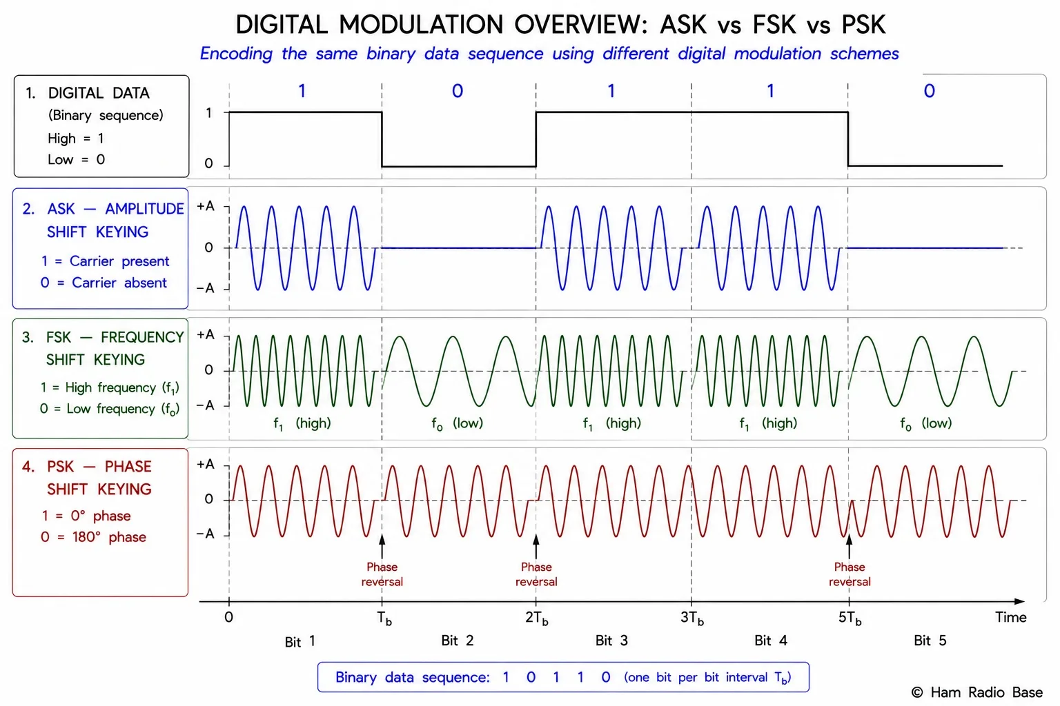
Amplitude-Shift Keying (ASK)
ASK varies the carrier amplitude to represent symbols. Binary ASK with levels {0, A} is on-off keying (OOK) — the simplest digital modulation scheme and the basis of Morse code CW. Multi-level ASK (4-ASK uses {0, A/3, 2A/3, A}; 8-ASK uses eight levels) encodes more bits per symbol at the cost of reduced noise margin.
ASK is very sensitive to amplitude-varying channel impairments: fading, multipath, and nonlinearities that distort amplitude all directly corrupt ASK symbols. This makes ASK poorly suited for HF radio channels but acceptable on highly controlled links (optical fiber, some wireline modems). OOK/CW succeeds on HF only because the receiver operates on a binary (on/off) basis — any signal above the noise threshold is decoded as a "1," so the absolute amplitude need not be known.
- Simplest implementation — varies only carrier amplitude
- Poor noise and fading immunity for multi-level variants
- OOK (binary ASK) is robust for simple threshold detection
- Occupied bandwidth ≈ symbol rate × (1 + rolloff factor)
Frequency-Shift Keying (FSK)
FSK switches the carrier frequency between M discrete values (tones) to represent M symbols. Binary FSK (2-FSK, BFSK) uses two frequencies f1 and f2 separated by a frequency shift Δf. The ratio of frequency shift to symbol rate is the modulation index h = Δf / fs.
When h = 0.5, the two FSK tones are orthogonal (their cross-correlation is zero) — this is Minimum-Shift Keying (MSK). MSK has the narrowest possible bandwidth for coherent binary FSK and produces a constant-envelope signal (no amplitude variation), making it suitable for nonlinear amplifiers. Gaussian MSK (GMSK) pre-filters the baseband data with a Gaussian filter before modulation, reducing spectral occupancy further at the cost of slight inter-symbol interference. GMSK is the modulation scheme used in GSM (2G cellular).
BW ≈ 2(Δf + fs)
where Δf = frequency deviation (half the total shift), fs = symbol rate
RTTY uses 2-FSK with mark/space frequencies separated by 170 Hz and a symbol rate of 45.45 Baud.
Δf = 85 Hz, fs = 45.45 Baud
BW ≈ 2(85 + 45.45) = ≈ 261 Hz
RTTY typically allocates 250–300 Hz of SSB passband.
4-FSK uses four tones to carry 2 bits/symbol. FT8 uses 8-GFSK (eight tones, Gaussian filtered) to carry 3 bits/symbol in a 50 Hz bandwidth at 6.25 Baud — an extraordinarily efficient combination achieved by very slow symbol rate and DSP-based tone discrimination.
Phase-Shift Keying (PSK)
PSK switches the carrier phase between M equally spaced values. BPSK (M=2) and QPSK (M=4) were covered in the Phase Modulation lesson. Higher orders:
- 8-PSK: 8 phases, 3 bits/symbol. Used in DVB-S2 satellite broadcasting and some HF modes.
- 16-PSK: 16 phases, 4 bits/symbol. Rarely used alone — 16-QAM achieves the same bits/symbol with better noise margin.
As M increases, adjacent constellation points get closer together (for fixed total power), reducing noise margin. PSK requires careful phase recovery (carrier synchronization) at the receiver — a phase-locked loop or Costas loop that tracks the incoming carrier phase. This complexity limits high-order PSK on channels with phase noise. PSK is constant-envelope (amplitude stays fixed), so it works well through nonlinear amplifiers.
Quadrature Amplitude Modulation (QAM)
QAM simultaneously varies both the amplitude and phase of the carrier, combining ASK and PSK on two orthogonal carriers (I and Q). A 16-QAM signal has 16 points arranged in a 4×4 rectangular grid in the I-Q plane — 4 amplitude levels on the I axis crossed with 4 amplitude levels on the Q axis. Each symbol carries log2(16) = 4 bits.
| Order | Grid | Bits/Symbol | Common Use |
|---|---|---|---|
| 4-QAM (= QPSK) | 2×2 | 2 | Satellite, 802.11 low MCS |
| 16-QAM | 4×4 | 4 | Cable, 802.11, HF ALE |
| 64-QAM | 8×8 | 6 | Cable TV, 802.11n/ac |
| 256-QAM | 16×16 | 8 | DOCSIS cable, 802.11ac/ax |
| 1024-QAM | 32×32 | 10 | Wi-Fi 6 (802.11ax) |
QAM requires both amplitude and phase accuracy — the receiver must know the exact amplitude and phase reference to distinguish adjacent constellation points. This makes QAM sensitive to nonlinearities (which distort amplitude) and phase noise (which rotates the constellation). High-order QAM (256-QAM and above) is only practical on channels with very high SNR (typically >30 dB for 256-QAM).
OFDM: Orthogonal Multi-Carrier Modulation
Orthogonal frequency-division multiplexing (OFDM) divides a wide bandwidth channel into many narrowband subcarriers, each carrying a low-symbol-rate signal. The subcarriers are spaced exactly at intervals of 1/Ts (where Ts is the symbol period) so that each subcarrier is at a zero crossing of every other subcarrier's spectrum — they are orthogonal. The received signal on each subcarrier can be recovered independently despite the overlapping spectra.
OFDM's key advantage: each narrow subcarrier experiences flat fading (nearly constant amplitude and phase across its bandwidth) even when the total channel exhibits frequency-selective fading. A guard interval (cyclic prefix) added to each symbol absorbs multipath echoes without causing inter-symbol interference. This makes OFDM the dominant modulation scheme for broadband wireless: 802.11a/g/n/ac/ax (Wi-Fi), 4G LTE, 5G NR, and digital TV (DVB-T) all use OFDM or its variants.
In amateur radio, Winlink Vara HF, FreeDV, and some SDR-based HF digital modes use OFDM subcarriers to combat the multipath and Doppler spread of ionospheric propagation.
Spread Spectrum
Spread-spectrum techniques deliberately spread a signal over a bandwidth much wider than the minimum required, trading spectral efficiency for interference immunity and coexistence capability.
Direct-Sequence Spread Spectrum (DSSS)
The data stream is multiplied by a pseudorandom noise (PN) code running at a much higher rate (the chip rate). The transmitted bandwidth equals the chip rate rather than the data rate. At the receiver, correlation with the same PN code de-spreads the signal, recovering the data while spreading any narrowband interferer across the full chip-rate bandwidth. The processing gain is the ratio of chip rate to data rate, typically 10–30 dB. DSSS is used in GPS, CDMA cellular, and 802.11b (Wi-Fi).
Frequency-Hopping Spread Spectrum (FHSS)
The carrier frequency hops among many channels in a pseudorandom sequence synchronized between transmitter and receiver. Each transmission occupies a narrow channel for a short dwell time, then hops. An interferer at a fixed frequency captures only the brief dwell intervals, causing partial-band interference rather than continuous jamming. FHSS is used in Bluetooth, 802.11 FHSS, and military communications.
Comparison Table
| Scheme | Bits/Symbol | Constant Envelope? | Sensitivity to Phase Noise | Sensitivity to Amplitude Variation |
|---|---|---|---|---|
| OOK / BASK | 1 | No | None | High |
| BFSK / MSK | 1 | Yes | Low | None |
| BPSK | 1 | Yes | Low | None |
| QPSK | 2 | Yes | Low-medium | None |
| 8-PSK | 3 | Yes | Medium | None |
| 16-QAM | 4 | No | Medium | Medium |
| 64-QAM | 6 | No | High | High |
| 256-QAM | 8 | No | Very high | Very high |
Digital Modes in Amateur Radio
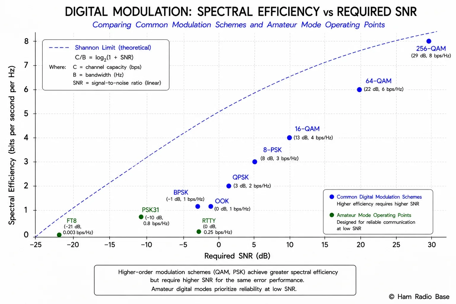
Amateur radio uses a remarkably diverse set of digital modulation schemes, often chosen not for spectral efficiency alone but for performance under the specific propagation challenges of each frequency band:
- FT8 (HF): 8-GFSK, 6.25 Baud, 50 Hz bandwidth. Optimized for marginal HF propagation; decodes at SNR as low as −21 dB.
- PSK31 (HF): DBPSK with raised-cosine shaping, 31.25 Baud, ≈31 Hz. Popular HF keyboard-to-keyboard chat mode.
- RTTY (HF): 2-FSK, 45.45 Baud, 170 Hz shift, ≈250–300 Hz bandwidth. Legacy teletype standard, still widely used in contests.
- JS8Call / Olivia (HF): MFSK variants (multi-tone FSK) designed for weak-signal operation and keyboard messaging.
- DMR / D-STAR / C4FM / NXDN (VHF/UHF): QPSK, GMSK, or 4-level FSK (4-FSK) voice/data digital voice modes used on repeaters and direct simplex.
- AX.25 Packet (VHF): AFSK (audio frequency-shift keying) at 1200 or 9600 Baud, used for APRS and packet bulletin boards.
Frequently Asked Questions
Why can't we always use 256-QAM to maximize data throughput?
256-QAM requires extremely high SNR — typically 30 dB or more — because 256 constellation points must be distinguishable in the presence of noise. On an HF radio channel, multipath fading and ionospheric distortion routinely cause SNR to vary by 20–30 dB within a single contact. At low SNR, 256-QAM produces catastrophic bit error rates. Adaptive modulation systems (used in Wi-Fi and LTE) solve this by monitoring channel quality and switching modulation order in real time — 256-QAM when SNR is high, BPSK when SNR is low — always operating at the highest sustainable rate. Amateur HF digital modes are typically designed for worst-case propagation, so they use low-order modulation (BPSK, QPSK, BFSK) for robustness.
What is the difference between symbol rate (baud) and bit rate?
Symbol rate (baud) is the number of symbol transitions per second. Bit rate is the number of bits delivered per second. They are equal only for binary modulation (1 bit/symbol). For M-ary modulation: bit rate = symbol rate × log2(M). A 16-QAM link running at 1,000 baud delivers 4,000 bits/s. The channel bandwidth is determined by the symbol rate, not the bit rate — which is why higher-order modulation improves spectral efficiency (more bits per unit bandwidth).
Why is FSK preferred over PSK on HF radio despite lower spectral efficiency?
PSK requires precise carrier phase recovery at the receiver — the demodulator must know the absolute phase of the received carrier to distinguish phase states. On an HF channel, ionospheric refraction introduces rapid phase variations that are difficult to track, especially at low SNR. FSK detection requires only identifying which of several frequencies is present — a frequency comparison that is much more robust to phase variations. RTTY (FSK) has survived on HF for decades because it works under conditions where PSK carrier recovery fails. More sophisticated PSK modes use differential encoding (DBPSK) or pilot tones to work around the phase recovery problem.
What is processing gain in spread spectrum and why does it matter?
Processing gain is the ratio of spread bandwidth to data bandwidth: Gp = Bspread / Bdata, expressed in dB as 10×log10(Gp). It represents how much narrowband interference is attenuated when the PN code de-spreads the received signal. A DSSS system with chip rate 10 MHz and data rate 100 kHz has processing gain = 10,000,000 / 100,000 = 100 = 20 dB. This means a narrowband interferer can be 20 dB stronger than the desired signal and still be rejected after despreading. Processing gain allows DSSS systems to operate in the presence of strong interference and enables multiple users to share the same bandwidth (CDMA).
How does FT8 decode signals at −21 dB SNR?
FT8 achieves this through several compounding techniques: (1) it uses a very slow symbol rate (6.25 Baud) to make each symbol last 160 ms, allowing long coherent integration times; (2) the message payload is compressed to 77 bits using a structured format (callsigns and grid squares are indexed, not sent as ASCII); (3) low-density parity-check (LDPC) forward error correction is applied — the transmitted frame is 174 bits for 77 data bits, providing 97 parity bits; (4) synchronization uses known Costas array tone sequences at known positions in the frame, enabling precise timing and frequency estimation. The combination allows the decoder to average signal energy over 12.6 seconds (one complete FT8 transmission cycle) while using powerful error correction to recover the message even when individual symbols are below the noise floor.
Test Your Knowledge
Answer the questions below to check your understanding of digital modulation.